Printing apparatus and cutter device

a cutting device and printing machine technology, applied in printing, metal working machines, other printing machines, etc., can solve the problems of fixed blades and moving blades slipping (locking) and achieve the effect of preventing slipping

Active Publication Date: 2018-01-04
SEIKO EPSON CORP
View PDF1 Cites 2 Cited by
  • Summary
  • Abstract
  • Description
  • Claims
  • Application Information

AI Technical Summary

Benefits of technology

[0006]An advantage of some aspects of the invention is to provide a printing apparatus including a cutter for cutting a printing medium by causing a moving

Problems solved by technology

In this case, there is a concern that the fix

Method used


Image

  • Printing apparatus and cutter device
  • Printing apparatus and cutter device
  • Printing apparatus and cutter device

Examples


Embodiment Construction

[0030]Hereinafter, an embodiment of the invention will be described with reference to the drawings. Such an embodiment does not limit the technical scope of the invention described in the claims.

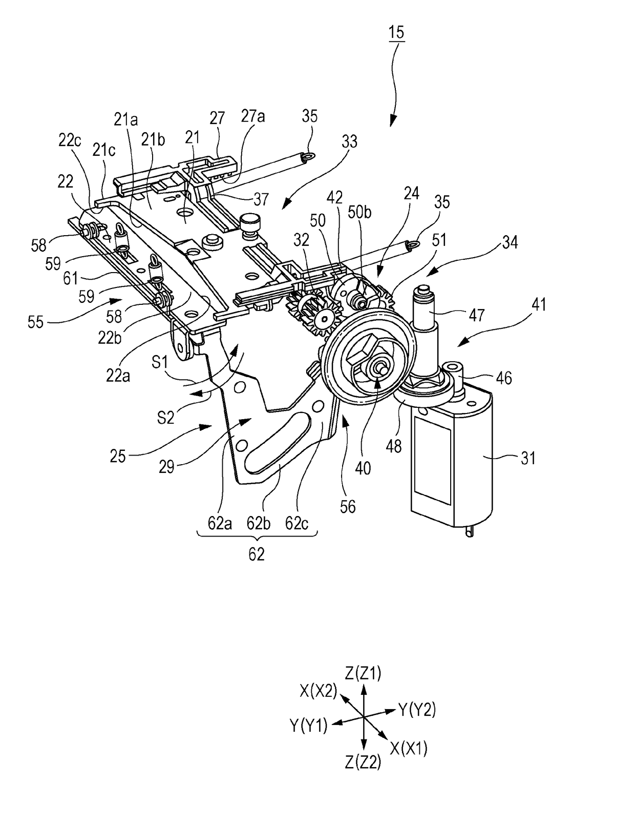
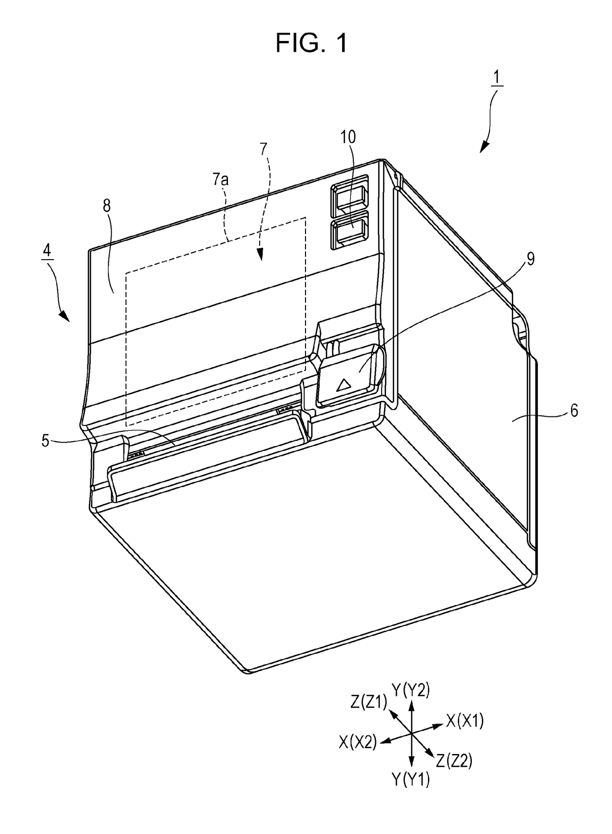
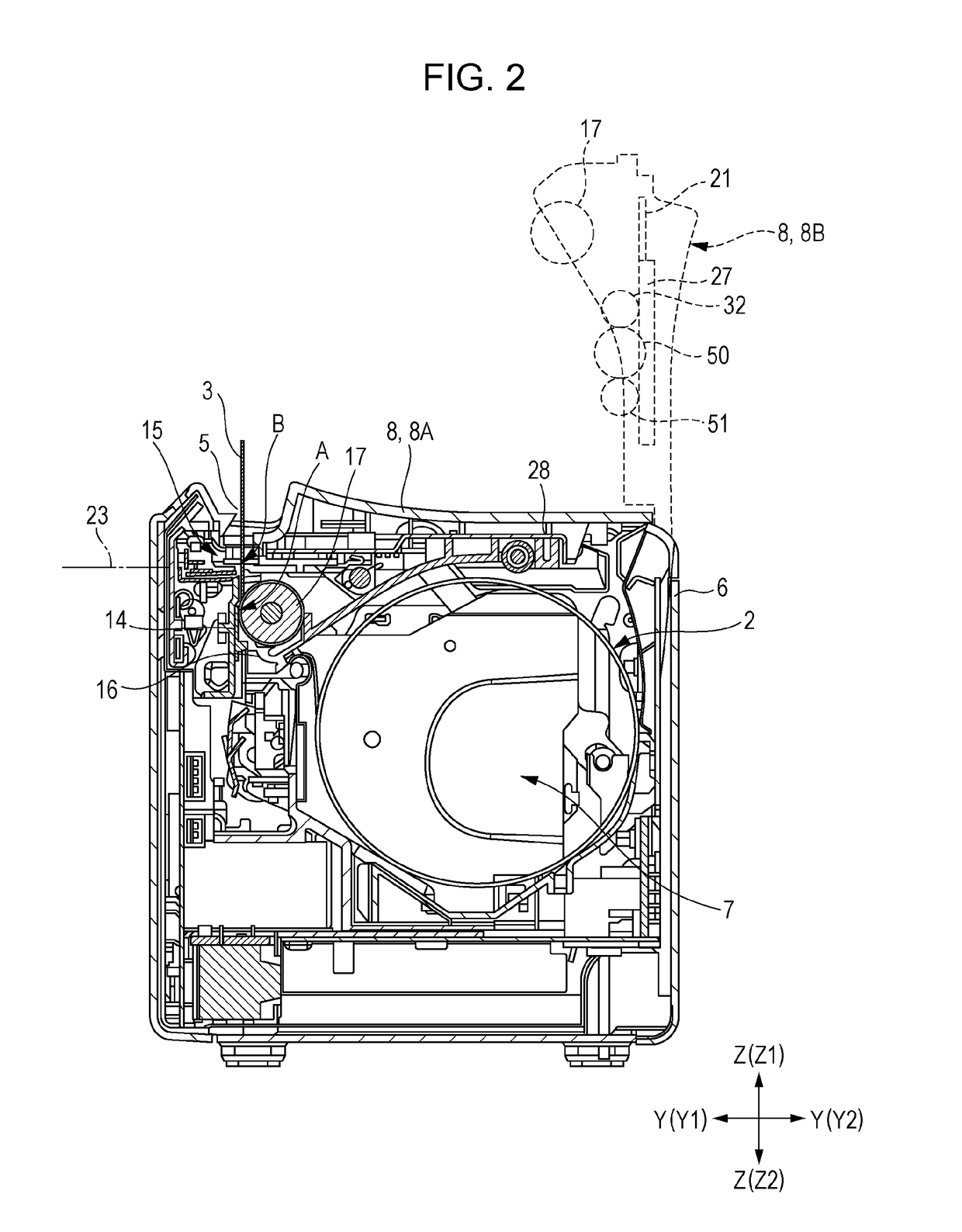
[0031]FIG. 1 is an external perspective view of a printing apparatus according to the embodiment to which the invention is applied. A printer 1 that is a printing apparatus to which the invention is applied includes a cutter 15 (cutter device, cutting device) for cutting a recording paper 3 (printing medium) by causing a first cutter blade 21 (moving blade, or first blade) to be in frictional contact (sliding) with a second cutter blade 22 (fixed blade, or second blade). In the cutter 15, it is possible to effectively prevent biting between the first cutter blade 21 and the second cutter blade 22 by positioning a rotation center C of the second cutter blade 22 on a first cutter blade 21 side with respect to a moving surface of the first cutter blade 21. Moreover, the second cutter blade 22 i...


PUM


Abstract

A printing apparatus includes a cutter. The cutter includes a first blade and a second blade, and cuts a printing medium by causing the first blade to be in frictional contact with the rotatable second blade to be moved, in which a rotation center of the second blade is disposed on a first blade side with respect to a moving surface of the first blade.

Description

BACKGROUND1. Technical Field[0001]The present invention relates to a printing apparatus including a cutter for cutting a printing medium by causing a moving blade to be in frictional contact (slide) with a fixed blade, or the like, and particularly, to a printing apparatus capable of effectively preventing biting between the fixed blade and the moving blade, or the like.2. Related Art[0002]In the related art, there is a printer including a cutter for cutting a sheet with a fixed blade and a moving blade. Such a cutter includes the fixed blade capable of being slightly moved by a rotating motion even while being biased toward the moving blade. In this case, in order to prevent biting (locking) between the fixed blade and the moving blade, a blade edge of the fixed blade is tapered.[0003]In JP-A-5-318385, a cutter in which a releasing mechanism of a movable blade and a fixed blade is provided in order to prevent occurrence of noise is described.[0004]However, in a case where a blade e...

Claims


Application Information

Patent Timeline
IPC IPC(8): B26D5/08B26D5/16B26D1/38B26D1/00B41J11/66B41J11/70
CPCB26D5/083B26D5/16B26D1/38B41J11/66B26D2001/0033B26D2001/0053B41J11/706B26D1/385B26D2001/0066
Inventor TOKUDA, TAKESHI
Owner SEIKO EPSON CORP
Why Eureka
Try Eureka