High Ping Rate Sonar

a sonar and high ping rate technology, applied in the field of sonar systems, can solve the problems of poor underwater environment resolution, slow refresh rate of marine electronic devices, and limited rate at which successive sonar beams are transmitted, and achieve the effect of high ping ra

Inactive Publication Date: 2018-01-11
NAVICO HLDG
View PDF44 Cites 10 Cited by
  • Summary
  • Abstract
  • Description
  • Claims
  • Application Information

AI Technical Summary

Benefits of technology

[0004]Example embodiments of the present invention provide apparatuses, methods, and computer-readable medium for high ping rate depth sounding. In an example embodiment, an apparatus comprises a processor and a memory including computer program code. The memory and the computer program code configured to, with the processor, cause the apparatus to cause transmission of a first sonar beam having a first frequency from a transducer assembly at a first time, wherein the transducer assembly is configured to transmit the first sonar beam into an underwater environment. The memory and the computer program code are further configured to, with the processor, cause the apparatus to cause transmission of a second sonar beam having a second frequency from the transducer assembly at a second time, wherein the transducer assembly is configured to transmit the second sonar beam into the underwater environment, and wherein the first time is prior to the second time. The memory and the computer program code are further configured to, with the processor, cause the apparatus to receive sonar return data from the transducer assembly beginning either simultaneously with transmission of the first sonar beam at the first time or prior to transmission of the second sonar beam at the second time, wherein the sonar return data is formed from sonar returns received by the transducer assembly and converted into the sonar return data. The memory and the computer program code are further configured to, with the processor, cause the apparatus to determine, based on sonar return data acquired after transmission of both the first sonar beam and the second sonar beam, that at least a portion of the sonar return data corresponds to the first sonar beam by determining that the sonar return data comprises the first frequency.
[0010]In some embodiments, the memory and the computer program code are further configured to, with the processor, cause the apparatus to apply an echo cancellation technique to sonar return data acquired during transmission of sonar beams, wherein the echo cancellation technique cancels at least a portion of the sonar return data corresponding to a frequency used for the transmission so as to cancel interference from the transmission of the sonar beam.

Problems solved by technology

In some instances, the rate at which successive sonar beams are transmitted (“ping rate”) by these sonar devices is limited by the travel speed of the sonar beams in the underwater environment.
This may result in slow refresh rates for a marine electronic device and poor resolution of the underwater environment.
This problem may be particularly noticeable in deep-water sounding, where travel times are substantially greater.

Method used


Image

  • High Ping Rate Sonar
  • High Ping Rate Sonar
  • High Ping Rate Sonar

Examples


Embodiment Construction

[0022]Exemplary embodiments of the present invention now will be described more fully hereinafter with reference to the accompanying drawings, in which some, but not all embodiments of the invention are shown. Indeed, the invention may be embodied in many different forms and should not be construed as limited to the exemplary embodiments set forth herein; rather, these embodiments are provided so that this disclosure will satisfy applicable legal requirements. Like reference numerals refer to like elements throughout.

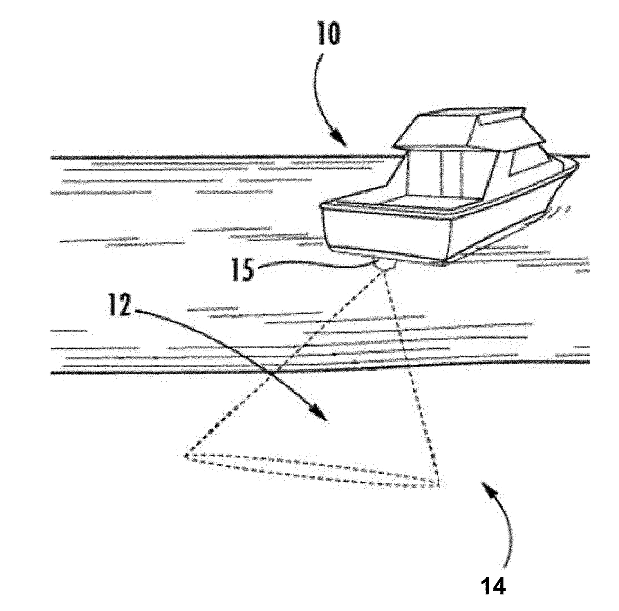
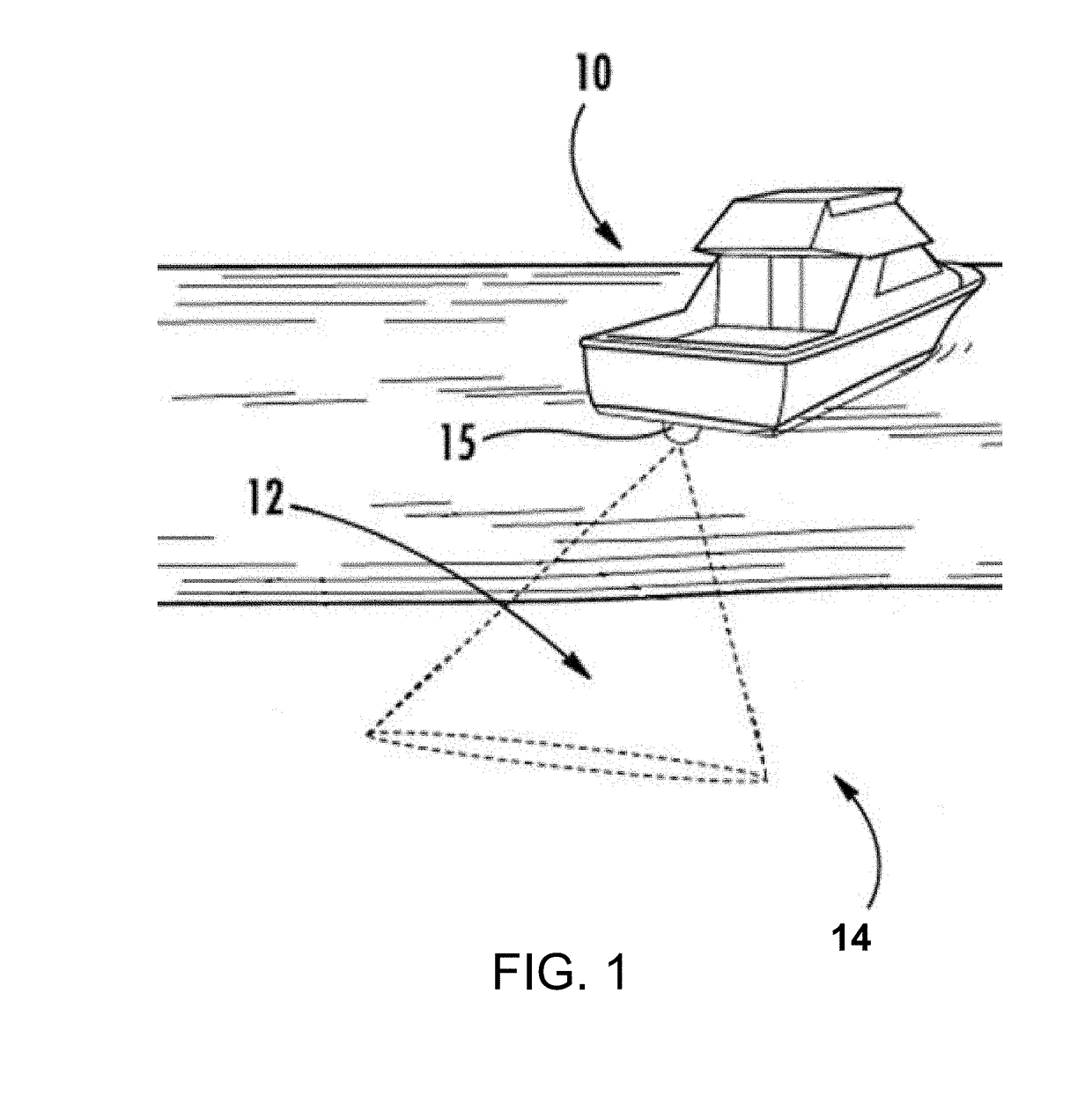
[0023]Sonar systems (e.g., sonar system 100 in FIG. 5) are commonly employed by boaters, sport fishermen, search and rescue personnel, researchers, surveyors, and others. With reference to FIG. 1, a watercraft 10 may include a sonar system that includes a transducer assembly 15. The transducer assembly 15 can be attached to the watercraft 10 and configured to transmit one or more sonar beams 12 (shown based on theoretical −3 dB range) into the underwater environment. So...


PUM


Abstract

An apparatus, method, and computer-readable medium for high ping rate depth sounding. The apparatus may cause transmission of a first sonar beam having a first frequency and transmission of a second sonar beam having a second frequency with a transducer assembly. The transducer assembly maybe configured to transmit the first sonar beam and the second sonar beam into the underwater environment. The apparatus may receive sonar return data from the transducer assembly beginning either simultaneously with transmission of the first sonar beam or prior to transmission of the second sonar beam. The apparatus may further determine, based on sonar return data acquired after transmission of both the first sonar beam and the second sonar beam, that the sonar return data corresponds to the first sonar beam by determining that the sonar return data comprises the first frequency.

Description

FIELD OF THE INVENTION[0001]Embodiments of the present invention relate generally to sonar systems and, more particularly, to sonar systems, assemblies, and associated methods for high ping rate sonar sounding.BACKGROUND OF THE INVENTION[0002]Sonar (SOund Navigation And Ranging) has long been used to detect waterborne or underwater objects. For example, sonar devices may be used to determine depth and bottom topography, detect fish, locate wreckage, etc. Sonar beams from a transducer assembly can be transmitted into the underwater environment. The sonar signals reflect off objects in the underwater environment (e.g., fish, structure, sea floor bottom, etc.) and return to the transducer assembly, which converts the sonar returns into sonar data that can be used to produce an image of the underwater environment.[0003]In some instances, the rate at which successive sonar beams are transmitted (“ping rate”) by these sonar devices is limited by the travel speed of the sonar beams in the ...

Claims


Application Information

Patent Timeline
Patent Type & Authority Applications(United States)
IPC IPC(8): G01S15/08G01S15/89G01S7/56G01S15/96G01S7/536
CPCG01S15/08G01S15/96G01S7/536G01S7/56G01S15/8902G01S7/523G01S15/89
Inventor MORALES, HECTORBARRERA, CRISTIAN
Owner NAVICO HLDG
Why Eureka
Try Eureka