Heart valve docking coils and systems

a technology of heart valve and coil, which is applied in the field of heart valve replacement and prosthetic heart valves, can solve the problems of fatal heart failure, mitral valve replacement is the size and shape of the native mitral annulus, and prolapse or eversion of the leaflets of the mitral valve back into the atrium, and achieves stable base or site, the effect of more robust way

Active Publication Date: 2018-03-01
EDWARDS LIFESCIENCES CORP
View PDF0 Cites 125 Cited by
  • Summary
  • Abstract
  • Description
  • Claims
  • Application Information

AI Technical Summary

Benefits of technology

[0020]Valve replacement can be realized through the use of a coiled anchor or docking device at the native valve site for docking an expandable transcatheter heart valve therein. The coiled anchors or docking devices provide a more stable base or site against...

Problems solved by technology

Due to the large pressure differential between the left ventricle and the left atrium during this time, a large amount of pressure is placed on the mitral valve, leading to a possibility of prolapse, or eversion of the leaflets of the mitral valve back into the atrium.
Various complications of the mitral valve can potentially cause fatal heart failure.
This can be caused, for example, by dilation of the left ventricle causing the native mitral leaflets to not coapt completely, resulting in a leak, by damage to the native leaflets, or weakening of (or damage to) the chordae tendineae and/or papillary muscles.
This discrepancy stems, in part, from replacement of a mitral valve being more difficult than aortic valve replacement in many respects, for example, due to the non-circular physical structure of the mitral valve, its sub-annular anatomy, and more difficult access to the valve.
One of the most prominent obstacles for mitral valve replacement is effective anchoring or retention of the valve at the mitral position, due to the valve being subject to a large cyclic load.
As noted above, another issue with mitral valve replacement is the size and shape of the native mitral annulus, as can be seen i...

Method used


Image

  • Heart valve docking coils and systems
  • Heart valve docking coils and systems
  • Heart valve docking coils and systems

Examples


Embodiment Construction

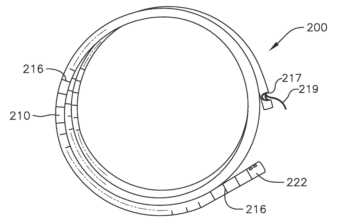
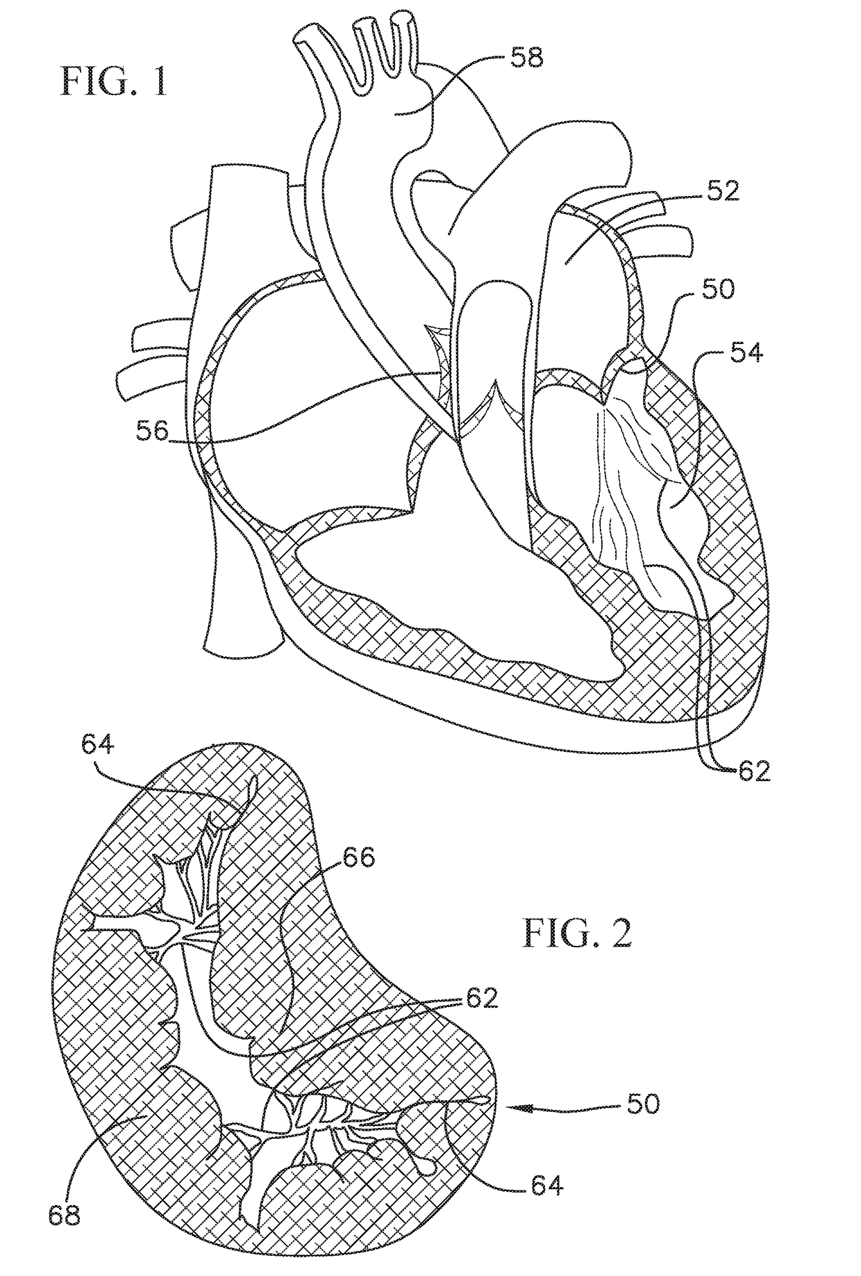
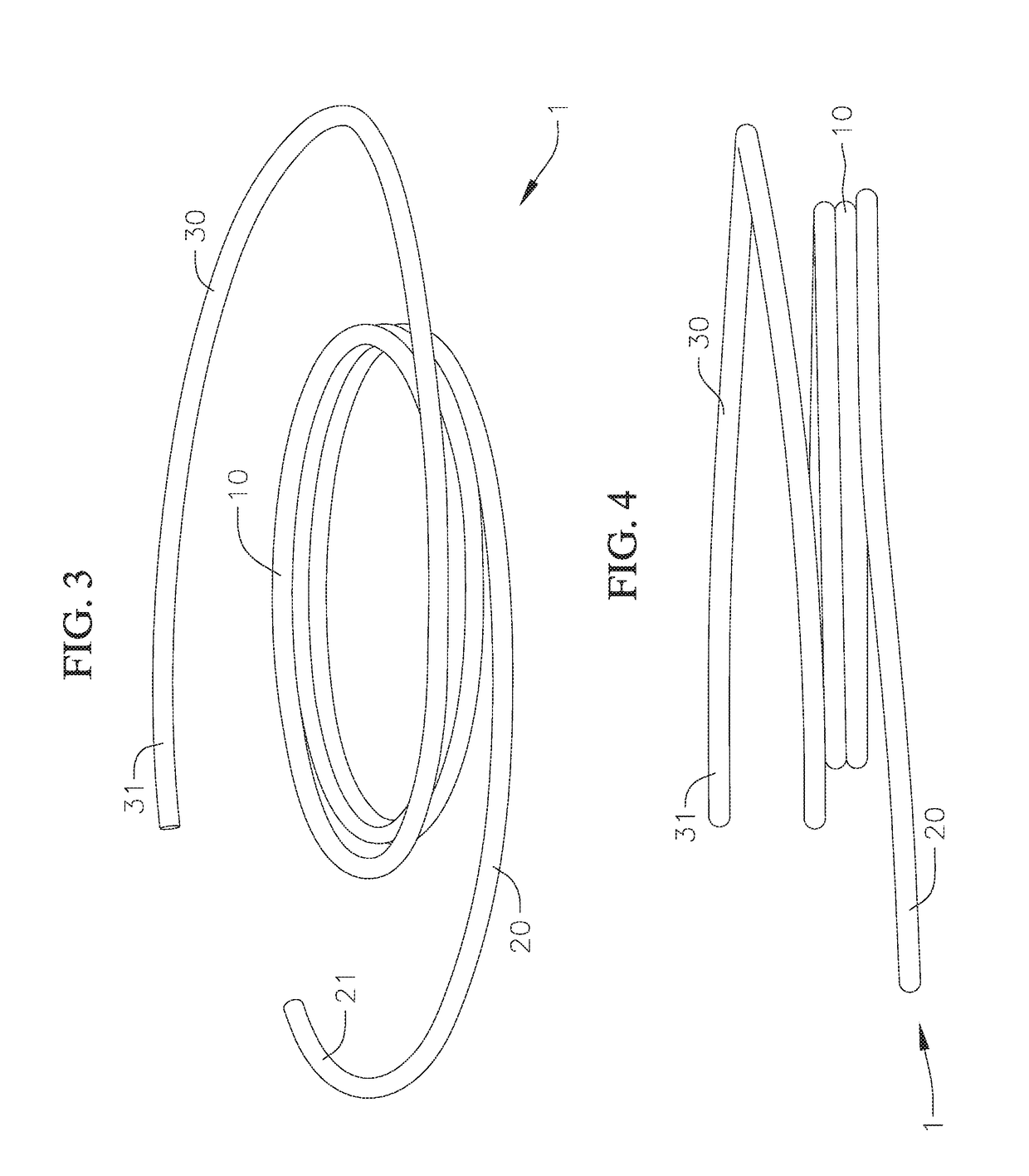
[0054]Disclosed herein are various coiled anchoring or docking devices, which can be used in conjunction with expandable transcatheter heart valves (THV) at a native valve annulus (e.g., mitral or tricuspid valve annulus), in order to more securely implant and hold the prosthetic valve at the implant site. Anchoring / docking devices according to embodiments of the invention provide or form a more circular and / or stable annulus at the implant site, in which prosthetic valves having circular or cylindrically-shaped valve frames or stents can be expanded or otherwise implanted. In addition to providing an anchoring site for the prosthetic valve, the anchoring / docking devices can be sized and shaped to cinch or draw the native valve (e.g., mitral, tricuspid, etc.) anatomy radially inwards. In this manner, one of the main causes of valve regurgitation (e.g., functional mitral regurgitation), specifically enlargement of the heart (e.g., left ventricle) and / or valve annulus, and consequent ...


PUM


Abstract

Anchoring or docking devices configured to be positioned at a native valve of a human heart and to provide structural support for docking a prosthetic valve therein. The docking devices can have coiled structures that define an inner space in which the prosthetic valve can be held. The docking devices can have enlarged end regions with circular or non-circular shapes, for example, to facilitate implantation of the docking device or to better hold the docking device in position once deployed. The docking devices can be laser-cut tubes with locking wires to assist in better maintaining a shape of the docking device. The docking devices can include various features to promote friction, such as frictional cover layers. Such docking devices can have ends configured to more securely attach the cover layers to cores of the docking devices.

Description

CROSS-REFERENCE TO RELATED APPLICATIONS[0001]This application claims priority to U.S. Provisional Patent Application Ser. No. 62 / 395,940, filed on Sep. 16, 2016. This application also claims priority to U.S. Provisional Patent Application Ser. No. 62 / 380,117, filed on Aug. 26, 2016. These two applications as well as U.S. patent application Ser. No. 14 / 372,953, entitled “Mitral Valve Docking Devices, Systems, and Methods,” filed on Jul. 17, 2014 are all incorporated herein by reference in their entireties.FIELD OF THE INVENTION[0002]The invention generally relates to medical devices and procedures pertaining to prosthetic heart valves. More specifically, the invention relates to replacement of heart valves that may have malformations and / or dysfunctions. Embodiments of the invention relate to an anchor or docking device that can hold and maintain a positioning of a prosthetic heart valve for replacing the function of a native heart valve, for example, for a mitral or tricuspid valve ...

Claims


Application Information

Patent Timeline
IPC IPC(8): A61F2/24
CPCA61F2/2409A61F2/2466A61F2/2427A61F2230/0091A61F2/2418A61B2017/00243A61B2017/0649A61F2/2436A61F2/2412A61F2230/0008A61F2250/0039A61F2250/0036
Inventor PATEL, DARSHIN S.MANASH, BOAZPERLMUTTER, KHENLEIBA, EYALROZEN, YOAVSIRIMANNE, DINESH L.
Owner EDWARDS LIFESCIENCES CORP
Why Eureka
Try Eureka