High speed modular sea base

Inactive Publication Date: 2003-08-26
THE UNITED STATES OF AMERICA AS REPRESENTED BY THE SECRETARY OF THE NAVY
View PDF5 Cites 4 Cited by
  • Summary
  • Abstract
  • Description
  • Claims
  • Application Information

AI Technical Summary

Benefits of technology

Another object of the invention is to provide a platform to travel at high speeds to a remote site and move portions of its hull a distance and fill air in volumes associated with the portions below the surface of the wate

Problems solved by technology

The long distances that must be traveled restrict the ability to respond quickly to local events due to time-on-station limitations, as well as response time.
Motel-like commercial accommodations require high construction costs and ar

Method used


Image

  • High speed modular sea base
  • High speed modular sea base
  • High speed modular sea base

Examples


Example

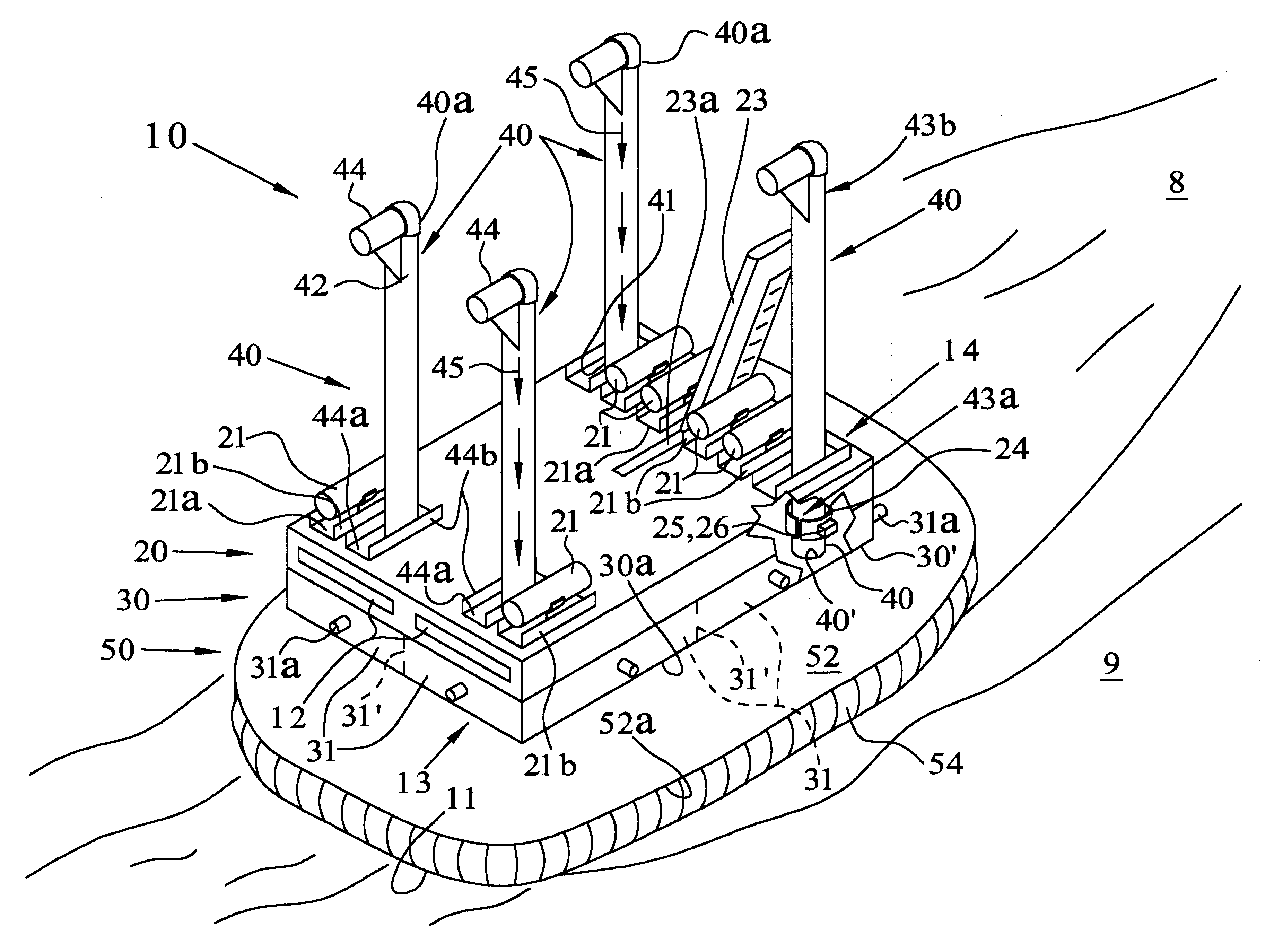
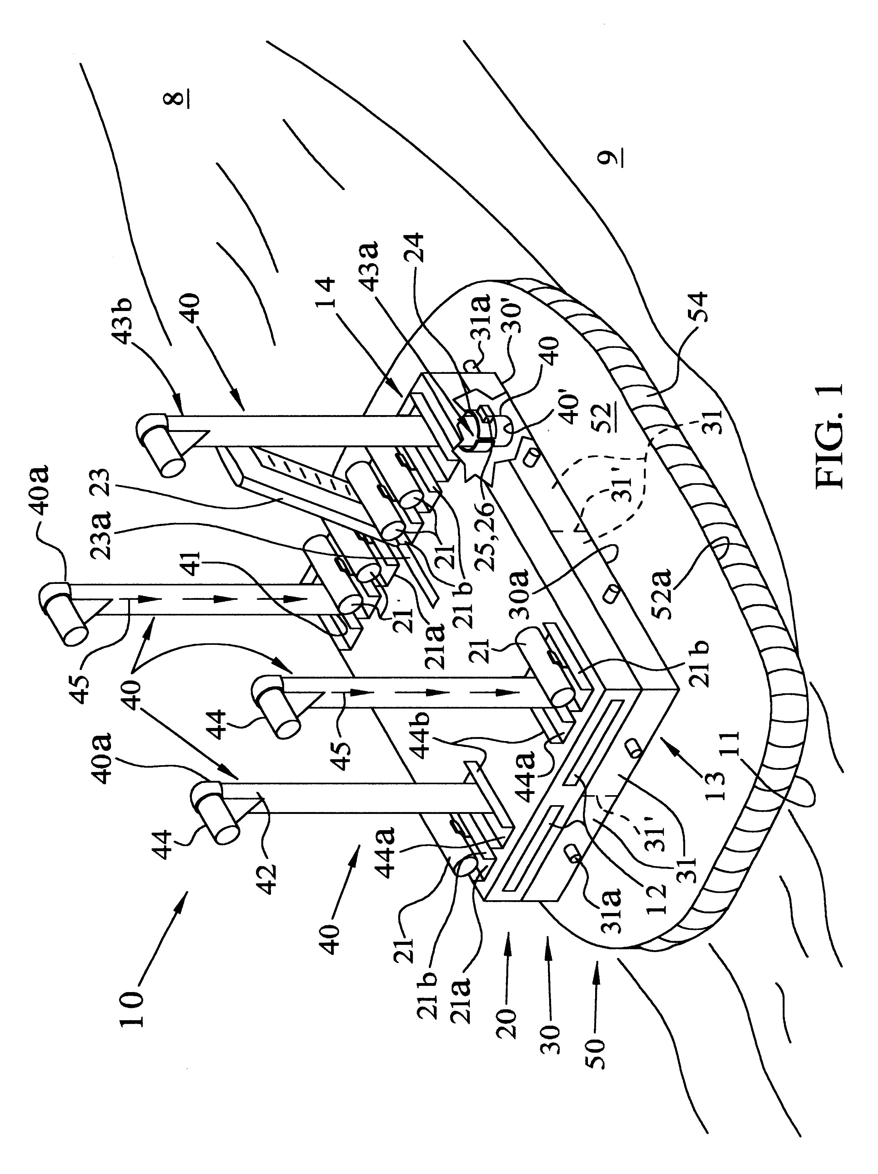
Referring to FIG. 1, modular platform 10 of the invention is schematically shown speeding across surface 8 of open water 9 at high speed on a pressurized cushion of air, or air cushion 11. Windows 12 extend across a forward portion 13 of platform 10 and provide a good vantage point for a crew for safe high-speed transit to a destination. Modular platform 10 has an upper level section 20 and a lower level section 30 below and adjacent to upper level section 20. Hollow struts 40 extend through upper level section 20, to and through lower level section 30, and to flexible skirt system 50. Flexible skirt system 50 is connected to lower periphery 30' of lower level section 30.

Upper level section 20 is buoyant to float on surface 8 if the need should arise and contains the spaces for propulsive and support machinery, navigation, command and control, living for personnel, and work areas with equipment for tasks and operations. Gas turbines 21 can be a part of the propulsive machinery and e...


PUM


Abstract

A high-speed modular platform has an upper level section having gas turbines on it for propulsion, and a lower level section has a lower periphery having a flexible skirt system connected to it to create an air cushion. Hollow struts extend between the upper level section and the lower level section. Each hollow strut is securely connected to the lower level section and has an opening communicating with a skirt volume inside of the flexible skirt system. Each hollow strut slideably engages the upper level section to permit sliding motion of the upper level section on the hollow struts toward and away from the lower level section. A gas turbine is connected to each of the hollow struts to vent, or force pressurized gas through them and create an air cushion with the flexible skirt system to enable high-speed transit over water and land surfaces and provide buoyancy.

Description

STATEMENT OF GOVERNMENT INTERESTSThe invention described herein may be manufactured and used by or for the Government of the United States of America for governmental purposes without the payment of any royalties thereon or therefor.This invention relates to systems for transporting loads and setting up a remote facility for military or commercial use. More particularly, this invention relates to an air cushion transportable structure for high-speed transit over the water or land and deployment on land or anchored offshore.Normal facilities such as warehouses, military / commercial staging areas, repair depots, and accommodations for personnel require a marine vessel or land-based real estate. Most ships have speeds of 20 to 30 knots and drafts that limit where they can be deployed, and land based in facilities are geographically constrained to one location.The success of many military operations, especially against the terrorist threat, requires rapid response with significant logist...

Claims


Application Information

Patent Timeline
IPC IPC(8): B60V1/04B60V1/00
CPCB60V1/04Y02T70/121Y02T70/10
Inventor CAVANAGH, RICHARD A.
Owner THE UNITED STATES OF AMERICA AS REPRESENTED BY THE SECRETARY OF THE NAVY
Why Eureka
Try Eureka