Pitch-variable spiral antenna

A technology of helical antenna and variable pitch, which is applied in the direction of antenna, loop antenna, antenna parts, etc., can solve the problems of complex equipment, installation environment influence, antenna loss increase, etc., and achieve good wide beam characteristics, good structural stability, Structurally Efficient Effects

Pending Publication Date: 2019-08-06
NO 54 INST OF CHINA ELECTRONICS SCI & TECH GRP
View PDF0 Cites 5 Cited by
  • Summary
  • Abstract
  • Description
  • Claims
  • Application Information

AI Technical Summary

Problems solved by technology

Microstrip antennas have the advantages of simple structure and low profile. Usually, high dielectric constant printed boards are used to reduce the size of the antenna aperture and meet the requirements of wide beams, but this will cause increased antenna loss and low antenna efficiency. At the same time, the wide-beam microstrip antenna is easily affected by the installation environment, resulting in deformation of the antenna pattern
When the cross dipole antenna is used as a wide beam antenna, the height of the antenna is high, and a circular polarization network needs to be added at the same time, so the equipment is relatively complicated
When the helical antenna is used as a wide-beam antenna, it is usually in the form of a four-arm helical antenna or a double-arm helical antenna. The four-arm helical antenna is small in size and compact in structure, and can achieve hemispherical radiation beams and good wide-angle axial ratio characteristics. The performance is less affected by the carrier, but the antenna bandwidth is narrow, which is not suitable for the use of broadband antennas; the dual-arm helical antenna has a compact structure, which can realize hemispherical radiation beams and good wide-angle axial ratio characteristics, and its radiation performance is less affected by the carrier. It is small and has good bandwidth characteristics at the same time, but the antenna height is relatively high. Therefore, it is necessary to study a circularly polarized wide-beam antenna form with simple structure, good wide-beam characteristics, and good bandwidth characteristics.

Method used


Image

  • Pitch-variable spiral antenna
  • Pitch-variable spiral antenna
  • Pitch-variable spiral antenna

Examples


Embodiment Construction

[0024] According to the attached Figure 1-5 The present invention is described further:

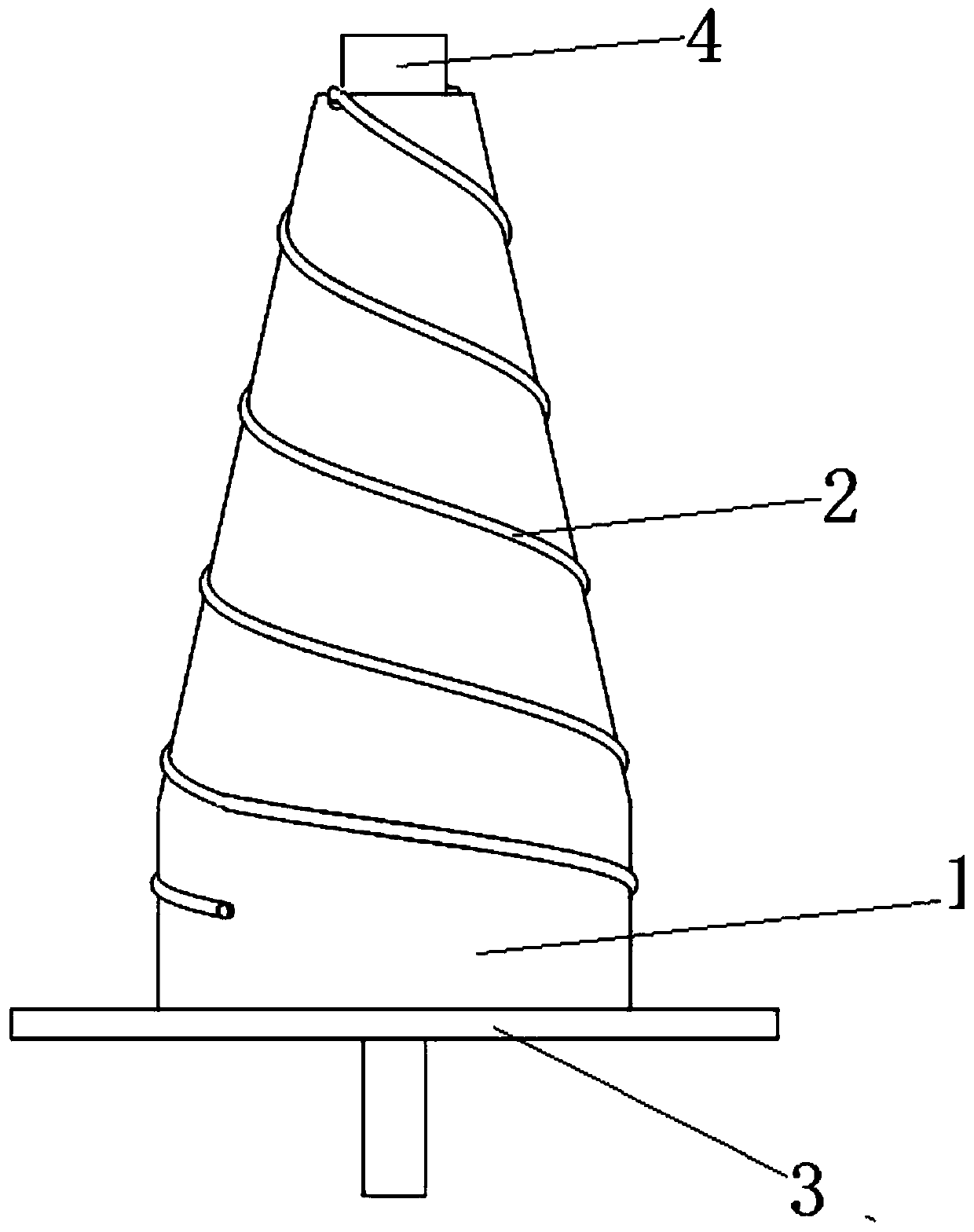
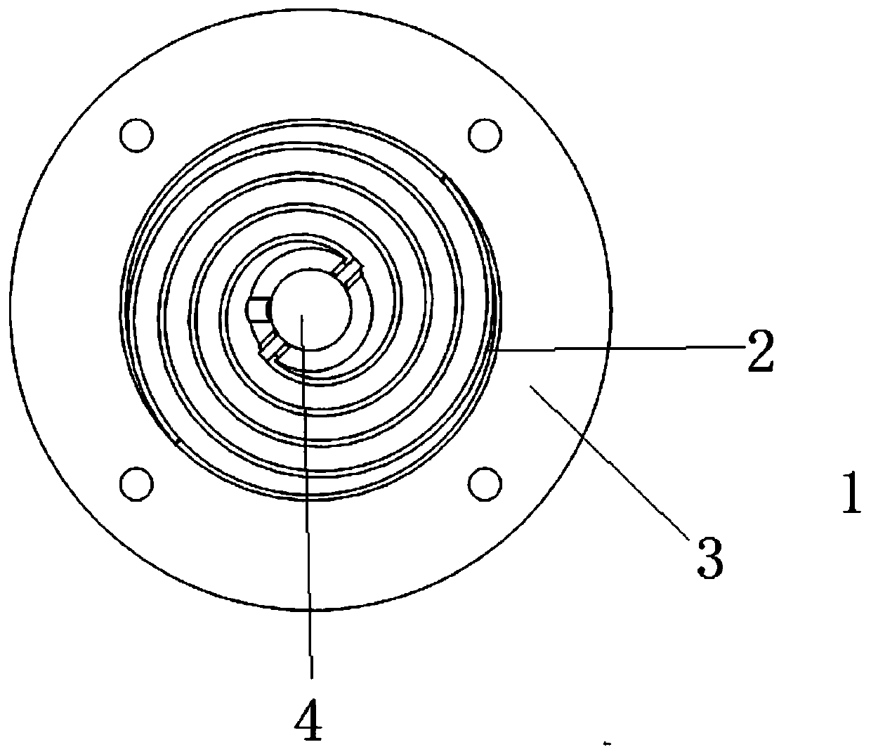
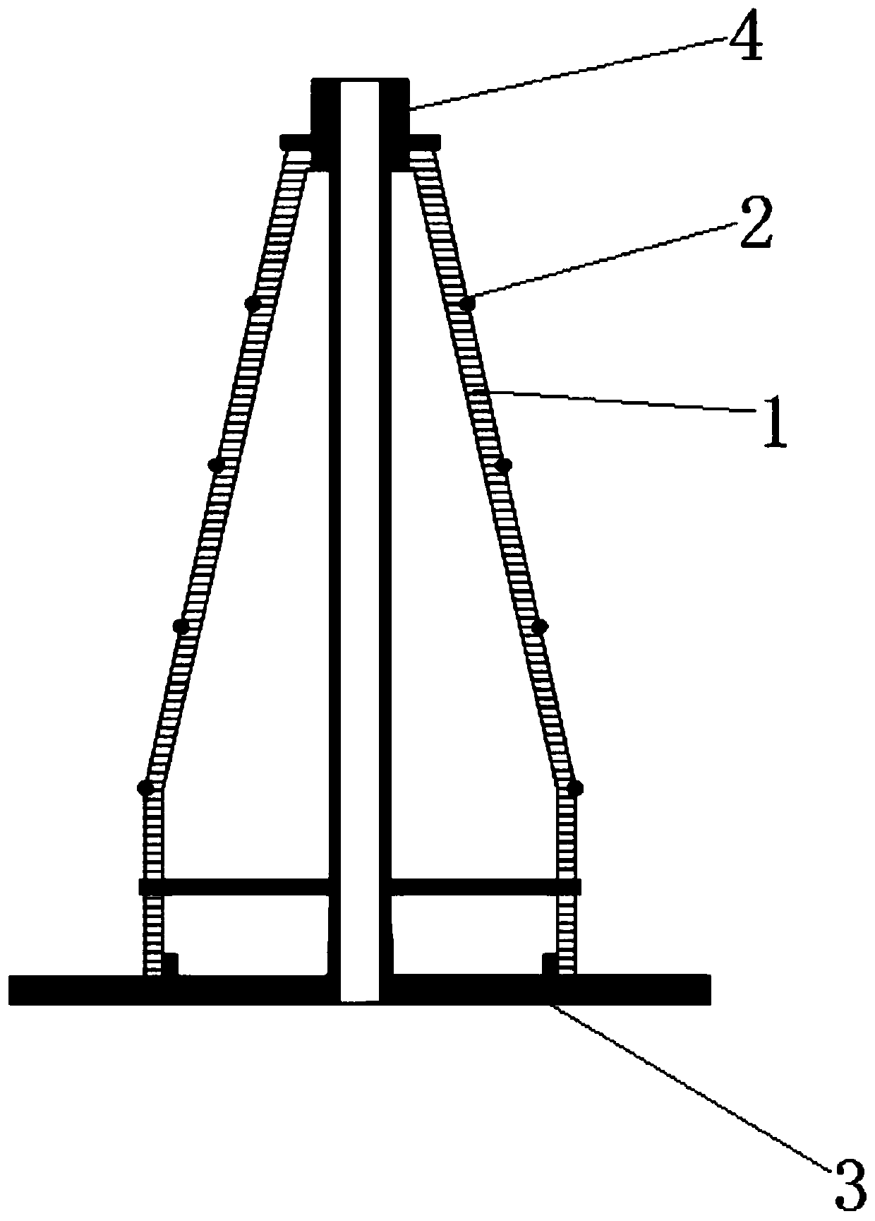
[0025] A variable-pitch helical antenna, including a base 3 as the main load, on which a medium support tube 1 is fixed. The medium support tube is a tapered hollow cylinder that gradually shrinks from bottom to top, and hovers on the medium support tube. Two rows of spiral arms 2 ascending in a spiral shape, and the two rows of spiral arms extend from the bottom of the medium support cylinder to the top of the medium support cylinder in anti-rotation;

[0026] A coaxial slotted balun 4 is coaxially pierced in the medium support cylinder, and the top and bottom ends of the two rows of spiral arms are respectively electrically connected to the coaxial slotted balun;

[0027] Such as figure 1 and Figure 5 As shown, the pitches of the two rows of helical arms are the same, and the pitches of each row of helical arms are variable pitches. The number of turns of the two rows of spiral ar...


PUM


Abstract

The invention discloses a pitch-variable spiral antenna. The antenna comprises a pedestal as a main bearing, a medium support cylinder fixed and positioned on the pedestal, two spiral arms rising in ahelical form on the medium support cylinder, and a coaxial grooved Balun coaxially positioned in the medium support cylinder in a penetrated way; the medium support cylinder includes a tapered hollowcylinder body whose aperture is reduced gradually from bottom to top; the two spiral arms extends from the bottom end to the top end of the medium support cylinder in the backward spinning direction;the top and bottom ends of each spiral arm are electrically connected with the coaxial grooved Balun; the spiral arms are the same in the pitch; and the pitch of each spiral arm is variable. Different steps are used to match different antenna bandwidths, and the wide wave beam feature of the whole antenna is ideal.

Description

technical field [0001] The invention belongs to the technical field of communication devices and relates to a helical antenna with variable pitch. Background technique [0002] At present, in the use of circularly polarized wide-beam antennas, there are mainly microstrip antennas, helical antennas, and other antenna forms. Microstrip antennas have the advantages of simple structure and low profile. Usually, high dielectric constant printed boards are used to reduce the size of the antenna aperture and meet the requirements of wide beams, but this will cause increased antenna loss and low antenna efficiency. At the same time, the wide-beam microstrip antenna is easily affected by the installation environment, resulting in deformation of the antenna pattern. When the cross dipole antenna is used as a wide-beam antenna, the antenna height is relatively high, and a circular polarization network needs to be added at the same time, so the equipment is relatively complicated. Whe...

Claims


Application Information

Patent Timeline
Patent Type & Authority Applications(China)
IPC IPC(8): H01Q1/12H01Q1/36H01Q1/50H01Q7/00
CPCH01Q1/1207H01Q1/36H01Q1/50H01Q7/00
Inventor 赵东贺汪显董长胜宁晓磊牛传峰段永强张廷恒任冀南王颖冀祯
Owner NO 54 INST OF CHINA ELECTRONICS SCI & TECH GRP
Why Eureka
Try Eureka