

Thread rolling assembly
a threaded fastener and assembly technology, applied in the direction of screw threads, other domestic articles, domestic applications, etc., can solve the problems of heavy metal components subject to wear and often requiring expensive adjustments and repairs, and the linear bearing used in the roll forming of threaded fasteners and other shapes has not been adapted,
- Summary
- Abstract
- Description
- Claims
- Application Information
AI Technical Summary
Benefits of technology
Problems solved by technology
Method used
Image


Examples
Embodiment Construction
[0024]The following disclosure as a whole may be best understood by reference to the provided detailed description when read in conjunction with the accompanying drawings, drawing description, abstract, background, field of the disclosure, and associated headings. Identical reference numerals when found on different figures identify the same elements or a functionally equivalent element. The elements listed in the abstract are not referenced but nevertheless refer by association to the elements of the detailed description and associated disclosure.
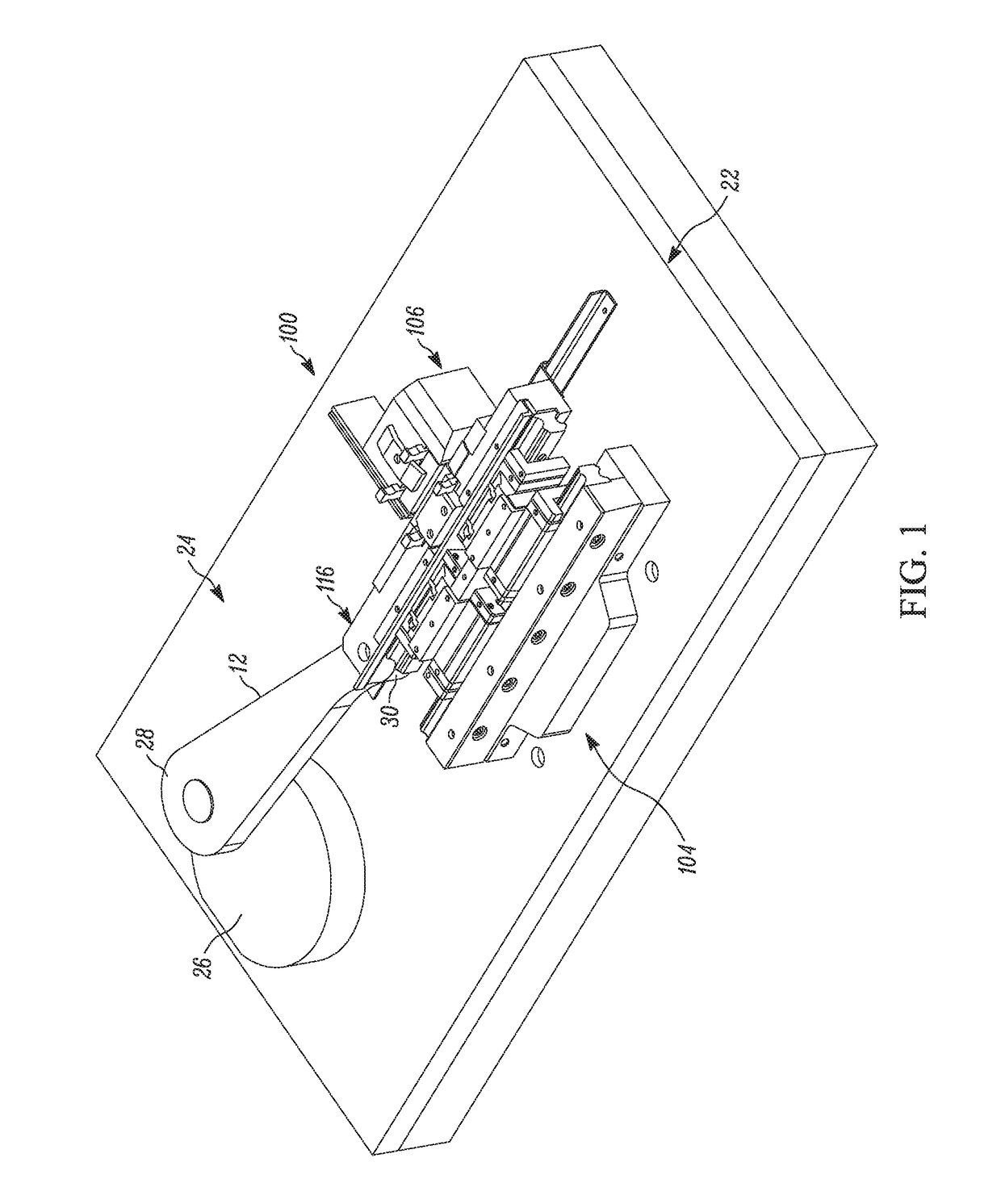
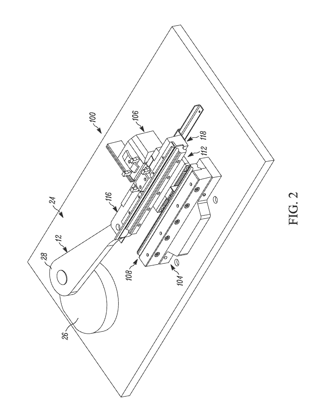
[0025]The present disclosure is directed to cold forming equipment directed to a thread rolling machine of advanced design utilizing aspects of currently available technology, such as light weight linear guideways in the form of rolling element linear motion bearings operating on re-circulating bearings and a gear reduction assembly that eliminates off-angle and reaction forces. Implementation of the disclosed equipment should revolutioniz...
PUM
 Abstract
Description
Claims
Application Information