
Flexible plate scale for platform load weighing

Active Publication Date: 2018-03-15
TEREX USA
View PDF25 Cites 6 Cited by
  • Summary
  • Abstract
  • Description
  • Claims
  • Application Information

AI Technical Summary

Benefits of technology

The present invention is a load bearing linkage connection that is both stiff and flexible. It consists of a sole pair of parallel steel load bearing plates that provide a connection between a platform support weldment and a platform rotator. The invention also includes an economically, computationally, and spatially efficient system for measuring the weight of the entire load on the AWP. Additionally, it provides a sole load cell for more repeatable results in weighing the load while simultaneously providing a more rigid connection to the boom.

Problems solved by technology

Many prior art AWP often failed to fully meet some of the industry needs.
One disadvantage of the four-bar linkage is that the pivot bearings introduce non-linear slop as well as stiction effects that create hysteresis in the load measurement.

Method used


Image

  • Flexible plate scale for platform load weighing
  • Flexible plate scale for platform load weighing
  • Flexible plate scale for platform load weighing

Examples


Embodiment Construction

[0039]Now referring to the drawings wherein like numerals refer to like structure shown in the drawings and text included in the application throughout.

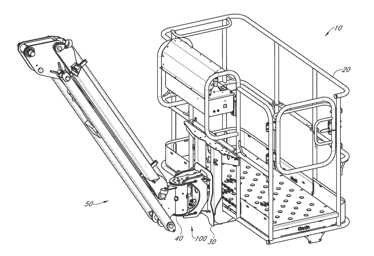
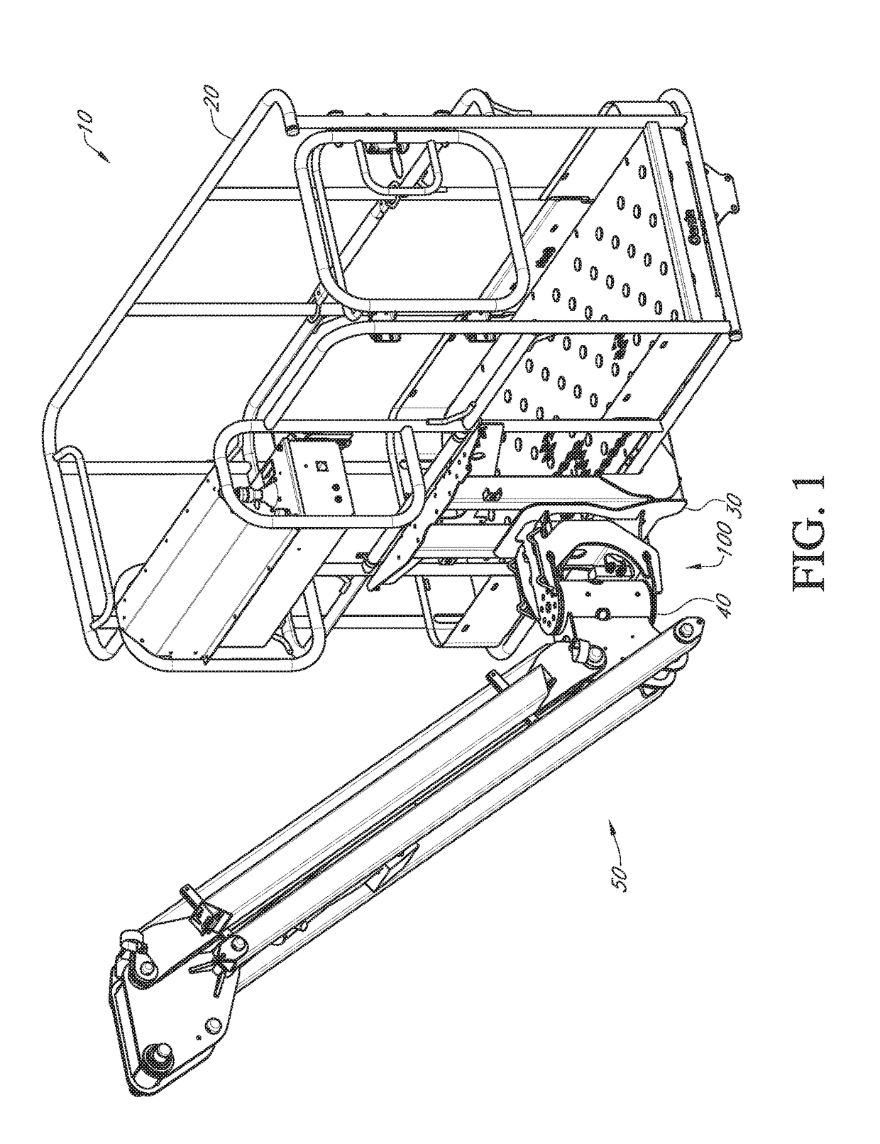
[0040]In FIG. 1, there is shown a basket 10 of an AWP with the three major substructures. A railing enclosure 20, which is similar to those which are well known in the art, which is attached to platform support structure 30, which is commonly used to provide support under a floor of a prior art bucket or basket. The innovative load sensing linkage system 100 is disposed between platform support structure 30 and platform rotator 40, which is coupled to boom 50.

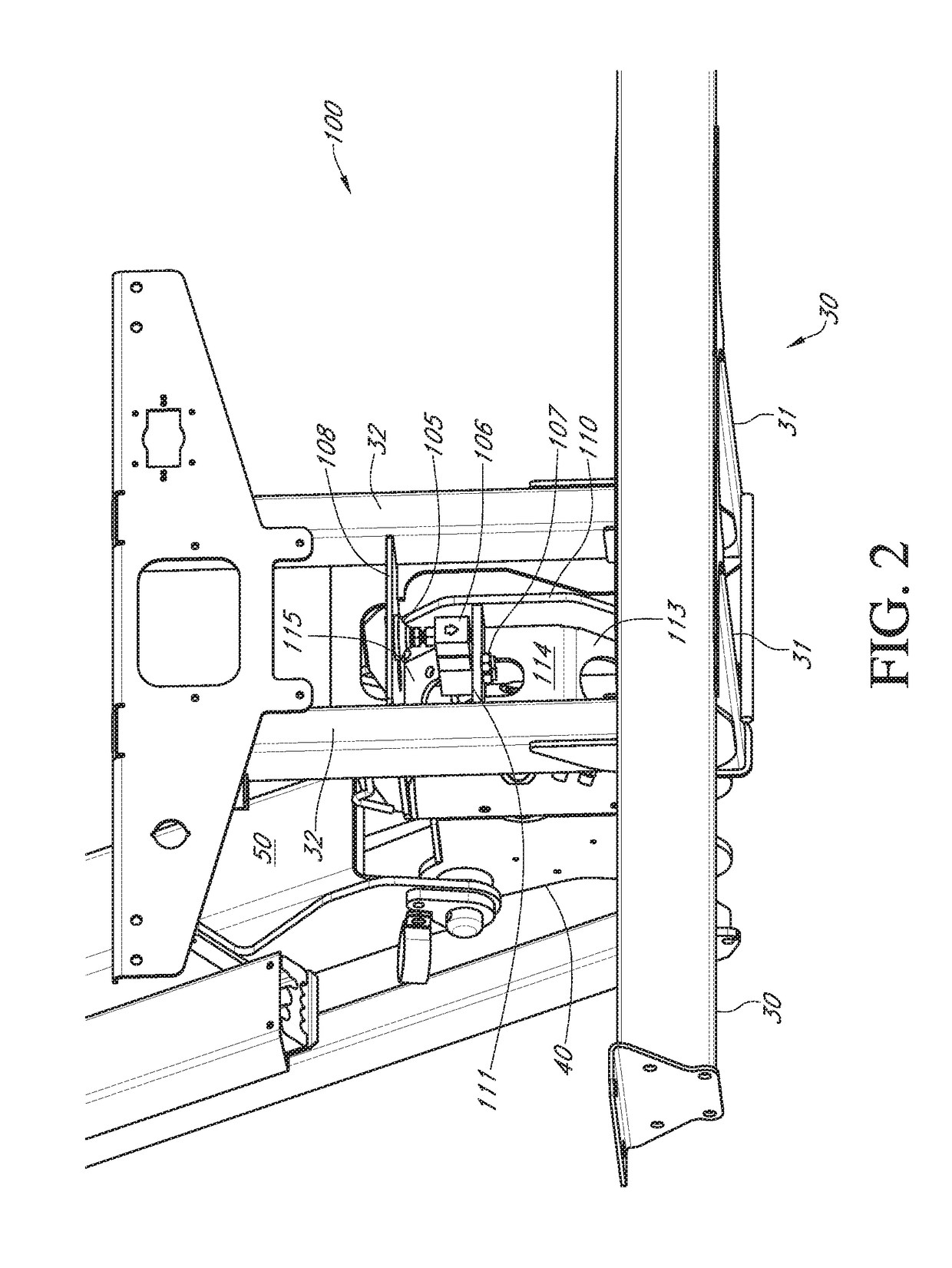
[0041]A better understanding of load sensing linkage system 100 can be obtained by now referring to FIG. 2, which shows a load end view with first C shaped linkage side 110 which is coupled to central load cell shelf 111 which is coupled to second C shaped linkage side 112 (FIG. 3). Load cell 106 is disposed on central load cell shelf 111 and is attached with load cell to suppor...


PUM


Abstract

An AWP boom is coupled to a platform rotator through a novel load sensing linkage system which provides both structural support and load sensing capabilities of an attached platform support structure. The load sensing linkage system includes an upper flex plate and a lower flex plate and a single load cell for load sensing capabilities. The flex plates provide for stiffness in all directions except where necessary for load sensing.

Description

CROSS REFERENCE TO RELATED APPLICATIONS[0001]The present application claims the benefit of the filing date of provisional patent application having Ser. No. 62 / 385,353 filed on Sep. 9, 2016 by the same inventors, which application is incorporated herein in its entirety by this reference.FIELD OF THE INVENTION[0002]The present invention relates to improved systems and methods for working from an elevated location.BACKGROUND OF THE INVENTION[0003]The present invention relates generally to aerial work platforms (AWPs) and more particularly to AWPs and methods of constructing and utilizing the same.[0004]More particularly, the present invention relates to systems and methods for accurately determining the weight of loads in a bucket or basket of an AWP. Many prior art AWP often failed to fully meet some of the industry needs. Often, baskets of AWPs require substantial rigidity to provide optimal utility and safety. However, prior art AWP (including U.S. Pat. No. 6,439,341) often used a ...

Claims


Application Information

Patent Timeline
IPC IPC(8): B66F17/00G01G23/18G01G19/52B66F11/04
CPCB66F17/006G01G23/18G01G19/52B66F11/044G01G19/083
Inventor CLARK, BRIAN M.LEUSCHKE, RAINER
Owner TEREX USA
Learn More