

Start-up of HVDC networks
- Summary
- Abstract
- Description
- Claims
- Application Information
AI Technical Summary
Benefits of technology
Problems solved by technology
Method used
Image

Examples
Embodiment Construction
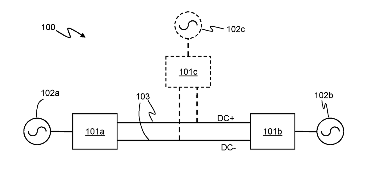
[0040]Embodiments of the present invention relate to methods and apparatus for control of voltage source converters (VSCs) for HVDC power transmission, and especially for start-up of a DC link between two or more VSCs that mitigates the problems of voltage oscillation on the DC link.
[0041]FIG. 1 illustrates an example of an HVDC power transmission / distribution network 100. A first VSC 101a is connected to a first AC system 102a and a second VSC 101b is connected to a second AC system 101b. The first and second VSCs are connected by a DC link 103, which is this example comprises DC lines at opposite polarities DC+ and DC−. It will be understood however that other arrangements are possible, including unipolar transmission. The first and second VSCs may be part of converter stations which, in some installations, may be relatively far apart. Thus the DC link 103 may comprise transmission lines, such as overhead transmission lines or buried or subsea cables, that may be many kilometres i...
PUM
 Abstract
Description
Claims
Application Information