Self-adjustable gas isolator
- Summary
- Abstract
- Description
- Claims
- Application Information
AI Technical Summary
Benefits of technology
Problems solved by technology
Method used
Image

Examples
embodiment 1
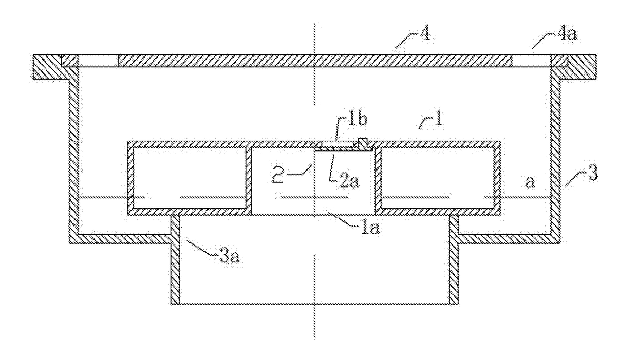
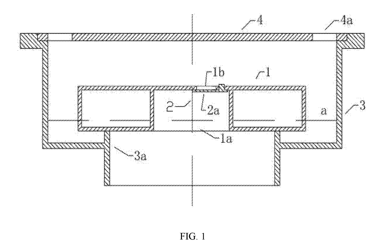
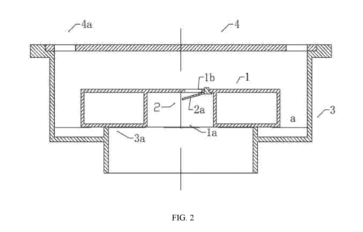
[0038]As shown in FIG. 1 and FIG. 2, the self-adjustable gas isolator of the embodiment 1 includes a floater 1, a pressure balancing device 2 and a liquid storage device 3; the floater 1 is provided with a groove 1a, and a pressure relief port 1b is arranged on the groove 1a; the pressure balancing device 2 comprises a first sealing element 2a; the liquid storage device 3 is provided with a liquid discharge opening 3a, and a liquid discharge hole 4a is arranged on the cover plate 4; the floater 1 is arranged in the liquid storage device 3, and the floater 1 floats in the liquid storage device 3; one end of the first sealing element 2a is arranged on the floater 1, and the other end of the first sealing element 2a is in sealing contact connection with the pressure relief port 1b.
[0039]The working process of the self-adjustable gas isolator described by the embodiment 1 is as follows: assuming the liquid storage device 3 is in a liquid with no buoyancy or in the initial state after t...
embodiment 2
[0043]As shown in FIG. 3, FIG. 4, FIG. 5 and FIG. 8 is the self-adjustable gas isolator of the embodiment 2, the basic structure of the present embodiment is the same as the embodiment 1, and the differences are as follows: the self-adjustable gas isolator further comprises a cover plate 4, the pressure balance device 2 comprises a fifth sealing element 2i, and the first sealing element 2a is omitted; a liquid discharging hole 4a is arranged on the cover plate 4, a convex block 4b is arranged on the cover plate 4 or the floater 1; one end of the fifth sealing element 2i is fixedly arranged on the floater 1, and the other end of the fifth sealing element 2i is in sealing contact connection with the pressure relief port 1b.
[0044]Liquid flows into the liquid storage device 3 through the liquid discharge hole 4a to enable the floater 1 to rise to be balanced, and the pressure borne by the pressure balancing device 2 is equal to the weight of the floater 1 and is smaller than the openin...
embodiment 4
[0045]As shown in FIG. 1, FIG. 3, FIG. 4, FIG. 5 and FIG. 6 is the self-adjustable gas isolator of the embodiment 4, the basic structure of the present embodiment is the same as that of the embodiment 1, the embodiment 2 and the embodiment 3, and the differences are as follows: the pressure balancing device 2 is changed into a spring type structure, comprising a second sealing element 2b, a spring 2c and an ejector rod 2f; two ends of the spring 2c are respectively arranged on the ejector rod 2f and the floater 1, the second sealing element is in sealing contact connection with the pressure relief port 1b.
[0046]When the floater 1 generates a negative pressure which is larger than the elastic force of the spring 2c, and the suction force of the negative pressure enables the spring 2c to deform, the second sealing element 2b opens the pressure relief port 1b which is in sealing contact connection. When the positive pressure liquid level rises and the top rod 2f is lifted to the cover...
PUM
 Abstract
Description
Claims
Application Information
 - R&D Engineer
- R&D Manager
- IP Professional
- Industry Leading Data Capabilities
- Powerful AI technology
- Patent DNA Extraction
Browse by: Latest US Patents, China's latest patents, Technical Efficacy Thesaurus, Application Domain, Technology Topic.
© 2024 PatSnap. All rights reserved.Legal|Privacy policy|Modern Slavery Act Transparency Statement|Sitemap