Panel with a fastening device

a technology of fastening device and panel, which is applied in the direction of fastening means, furniture joining, fitting, etc., can solve the problem of time-consuming and labor-intensive assembling of furniture components to furnitur

Active Publication Date: 2018-04-26
VÄLINGE INNOVATION AB
View PDF17 Cites 46 Cited by
  • Summary
  • Abstract
  • Description
  • Claims
  • Application Information

AI Technical Summary

Benefits of technology

[0006]An advantage of the invention may be that the fastening device may be locked to the panel without tools.
[0007]The insertion groove preferably extends from the panel surface to the edge groove. The insertion groove may be a bottom-ended groove, such as a bottom ended drill hole, comprising a bottom surface which is positioned at a distance from the edge groove.
[0008]The element may comprise two or more of said protruding part and the panel surface may comprise two or more of said insertion groove. The insertion grooves are preferably arranged linearly. Each of the protruding parts is configured to be inserted into one of the insertion grooves.
[0009]The edge groove may be a longitudinal groove that extends in a longitudinal direction of the edge surface and edge groove may be covered by e.g. an edging.
[0010]The edge groove preferably extends from the edge surface to the insertion groove. The edge groove is preferably a bottom-ended groove, comprising a bottom surface which is positioned at a distance from the edge groove. The flexible tongue may be arranged at the bottom surface of the edge groove.
[0011]The flexible tongue may be arranged between the recess and the bottom surface of the edge groove in a locked position of the fastening device and the panel.

Problems solved by technology

A drawback with the known systems is that it time consuming to assemble the furniture components to the furniture.

Method used


Image

  • Panel with a fastening device
  • Panel with a fastening device
  • Panel with a fastening device

Examples


Embodiment Construction

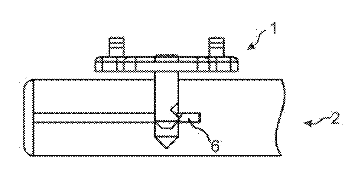
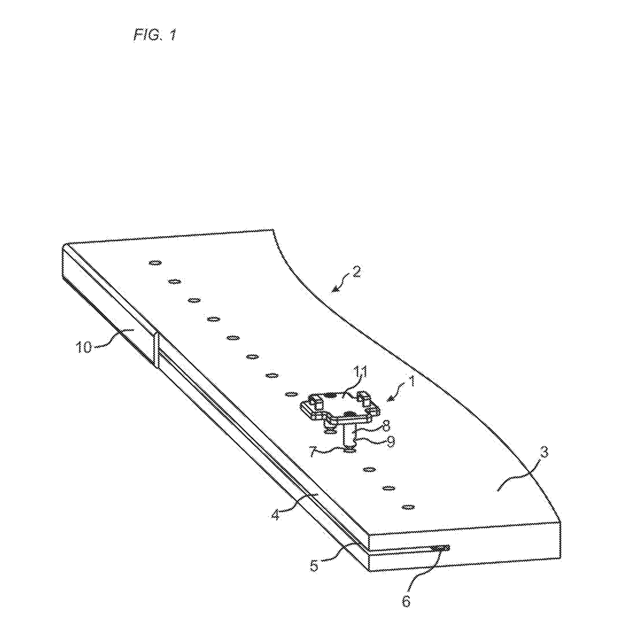
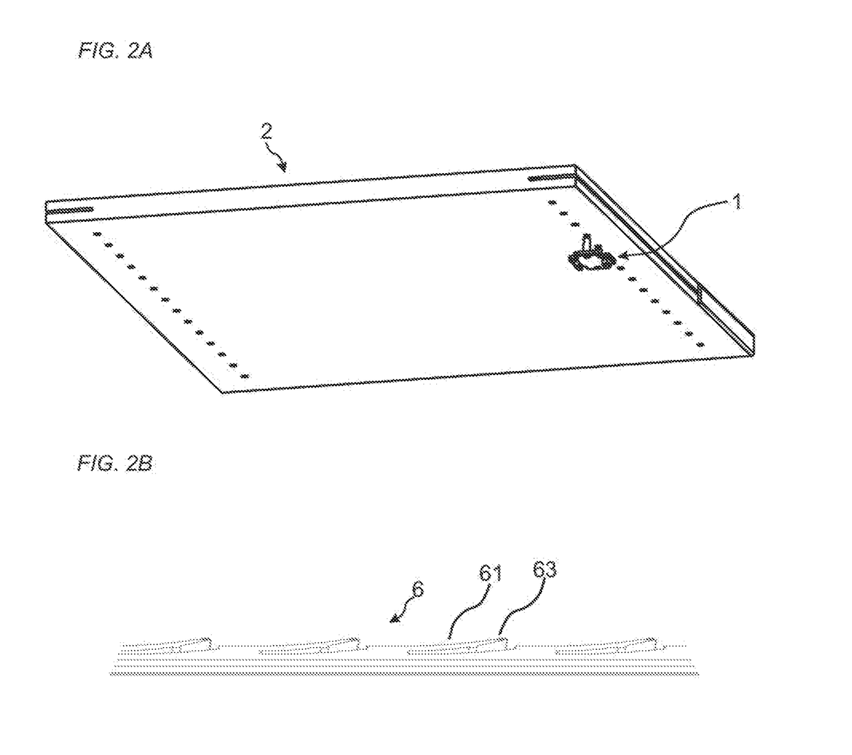
[0025]An embodiment of the invention is shown in FIG. 1. The embodiment comprises a panel 2 and a fastening device 1 for securing a furniture component, such as a hinge, an interior fitting, a carrying device or a slider, to the panel 2. The fastening device 1 comprises an element 11 with a first element surface 12 comprising two protruding parts 8 which protrudes from the element surface 12, even though the element surface may comprise one or several protruding parts. The panel comprises an edge surface 4 and a panel surface 3, which is the main surface of the panel. FIG. 1 shows only a part of the panel in a 3D-view. The whole panel is shown in a 3D-view in FIG. 2A. The panel surface comprises a row of insertion grooves 7 adjacent the edge surface 4. The panel surface may comprise one or several insertion grooves. The fastening device 1 is configured to be assembled to the panel with the first element surface 12 facing the panel surface 3. The edge surface 4 comprises an edge groo...


PUM


Abstract

A set comprising a panel and a fastening device for securing a furniture component, such as a hinge, an interior fitting, a carrying device or a slider, to the panel. The fastening device includes an element with a first element surface comprising a protruding part which protrudes from the first element surface. The panel comprises an edge surface and a panel surface, which includes an insertion groove. The fastening device is configured to be assembled to the panel with the first element surface facing the panel surface. The edge surface includes an edge groove and a flexible tongue is arranged in the edge groove. The protruding part is configured to be inserted into the insertion groove and includes a recess and the flexible tongue is configured to cooperate with the recess for a locking of the fastening device to the panel.

Description

TECHNICAL FIELD OF THE INVENTION[0001]The present invention relates to a fastening device for connecting a furniture component to a panel.TECHNICAL BACKGROUND[0002]Furniture components are known that are fixed to e.g. a furniture panel by screws. A drawback with the known systems is that it time consuming to assemble the furniture components to the furniture.[0003]The above description of various known aspects is the applicant's characterization of such, and is not an admission that any of the above description is considered as prior art.SUMMARY OF THE INVENTION[0004]It is an object of certain embodiments of the present invention to provide an improvement over the above described techniques and known art. Particularly to reduce the time for assembling and to provide a to provide a tool-less assembling.[0005]At least some of these and other objects and advantages that will be apparent from the description have been achieved by a first aspect of the invention that comprises a set comp...

Claims


Application Information

Patent Timeline
Patent Type & Authority Applications(United States)
IPC IPC(8): F16B12/26F16B12/10
CPCF16B12/26F16B12/10A47B2230/12A47B88/43F16B21/186A47B88/423Y10T403/4602A47B95/00A47B96/20A47B2220/0072F16B12/24A47B96/201
Inventor BOO, CHRISTIANDERLOV, PETER
Owner VÄLINGE INNOVATION AB
Why Eureka
Try Eureka