LED lamp device

Inactive Publication Date: 2008-10-14
PYROSWIFT HOLDING CO LIMITED
View PDF5 Cites 101 Cited by
  • Summary
  • Abstract
  • Description
  • Claims
  • Application Information

AI Technical Summary

Benefits of technology

[0009]The invention is mainly to provide an LED lamp device capable of focusing light sources, by arranging three rows of LED lamp sets as light-emitting source in a lampshade improved with curved angles, making the light-emitting pathways of these three rows of LED lamp sets may be focused, so not only the problem of the light-source dispersal caused by the flatness of lampshade is solved, but also the light-emitting performance is also improved by reflecting the light-emitting sources completely.
[0010]The invention is to provide an LED lamp device having a lamp seat, in which a lamp trough is formed by being recessed inwardly, and the inner edge surface of the lamp seat is formed

Problems solved by technology

Besides, the light-emitting effect of an LED is uneasy to disperse, compared with that of traditional light-emitting element.
Since the purpose of a streetlamp installed along a roadside is to guide people and vehicle, so its illuminating need is more severe than that of an indoor lamp.
Even being reflected by the lampshade, the light source generated from a traditional light-emitting element is still easily dispersed, so its illuminating effect is limited, particularly, under unstable weather conditions, the illuminating effect of the streetlamp being frequently influenced by mist or rain so greatly

Method used


Image

  • LED lamp device
  • LED lamp device
  • LED lamp device

Examples


Embodiment Construction

[0019]In cooperation with attached drawings, the technical contents and detailed description of the present invention are described thereinafter according to a preferable embodiment, being not used to limit its executing scope. Any equivalent variation and modification made according to appended claims is all covered by the claims claimed by the present invention.

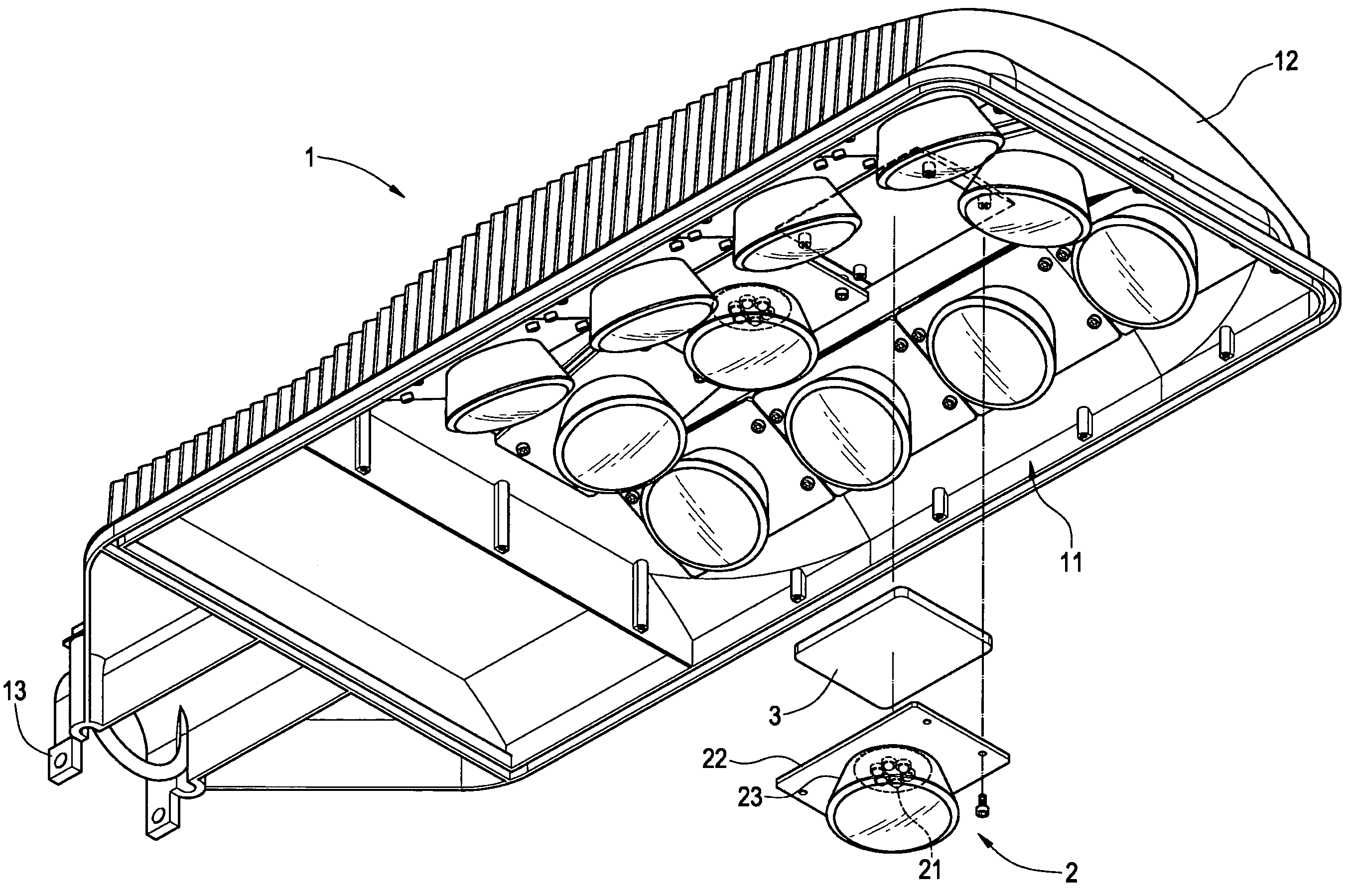
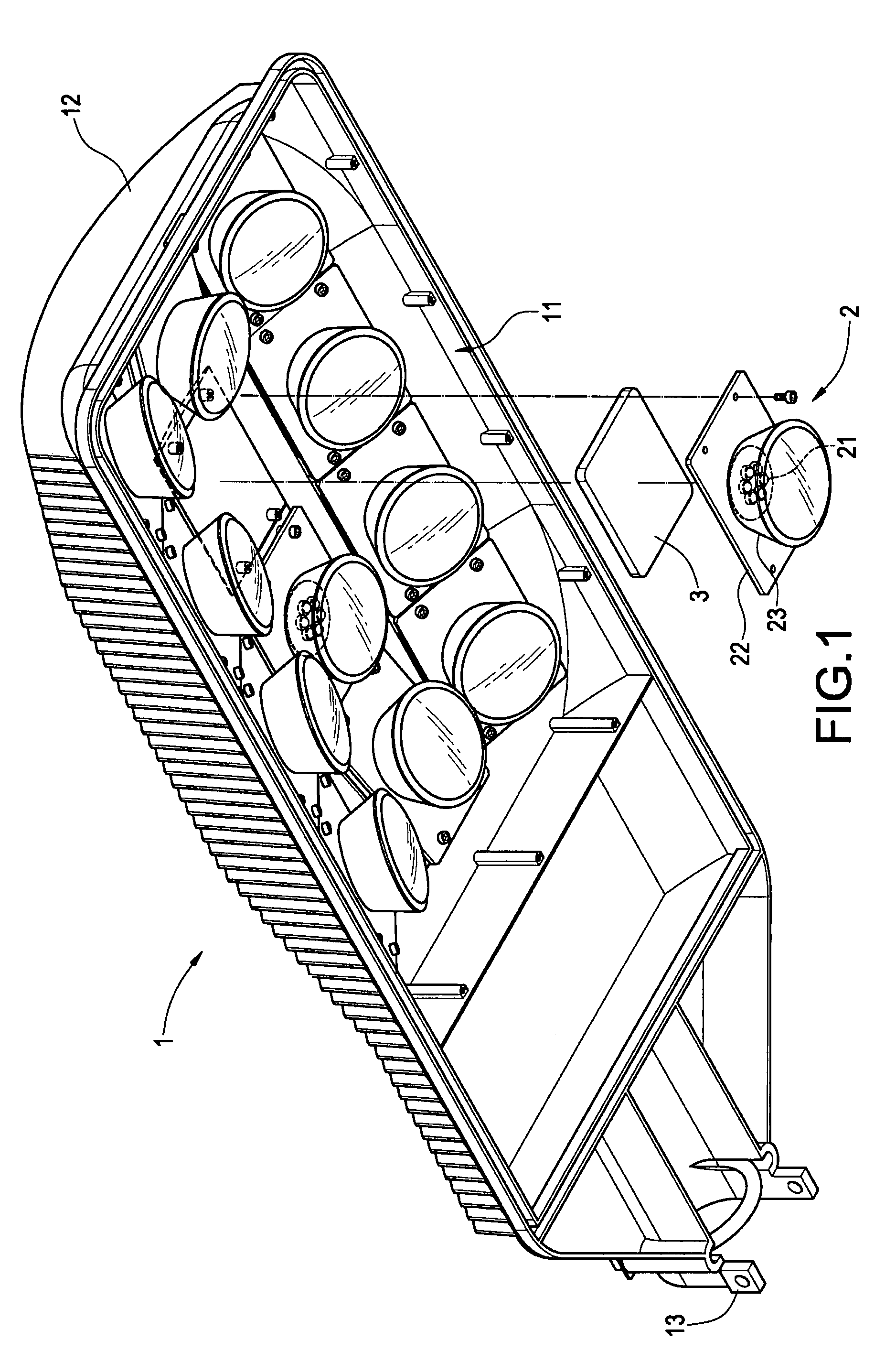
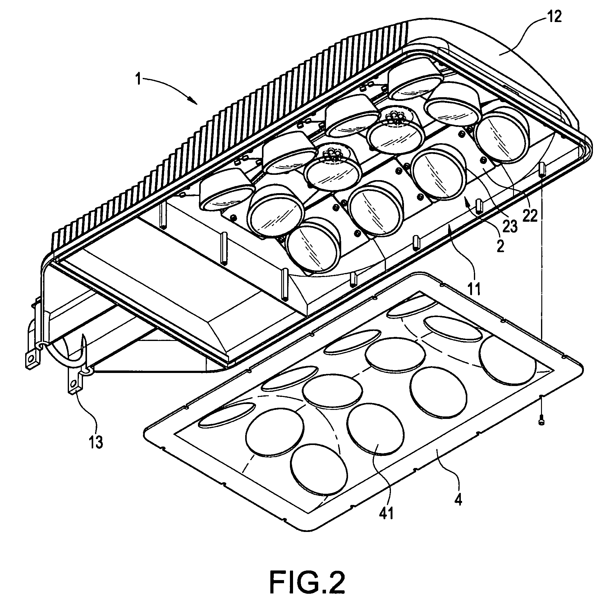
[0020]Please refer to FIG. 1, which is a perspective, explosive view of the structure of the present invention. As shown in this figure, a lamp device of the present invention mainly includes a lamp seat 1, which is shown as a rectangular casing integrally die-cast from an aluminum material. The bottom surface of the lamp seat 1 is recessed inwardly to form a lamp trough 11, which is shown as an arc surface in this embodiment and can be best shown in FIG. 6, which is a partially cross-sectional view of the present invention. The longitudinal sides of the lamp trough 11 are also bent inwardly to make the inner edge surface o...


PUM


Abstract

An LED lamp device has a lamp seat, in which a lamp trough is formed by being recessed inwardly, and the inner edge surface of the lamp seat is formed as an arc surface. The front and rear parts in longitudinal direction of the lamp trough are also bent inwardly. Three rows of lamp set are arranged along the longitudinal sides in the lamp trough. These lamp sets have a plurality of LEDs as light-emitting elements. The lamp sets at left and right rows are inclined inwardly according to the curvature of the inner edge surface. In the meantime, the lamp sets at front and rear sides of one row are also inclined inwardly. Under this arrangement, the plural lamp sets not only can enhance the illumination of the lamp, but also can concentrate its light-emitting operation, for solving a shortcoming of light dispersal in most light sources.

Description

BACKGROUND OF THE INVENTION[0001]1. Field of the Invention[0002]The present invention generally relates to a lamp, in particular, to a lamp device taking Light-Emitting Diode (LEDs) as light-emitting elements.[0003]2. Description of Prior Art[0004]It is no doubt that LED has become one of the products attracting most attention in recent years, thanks to its advantages of low pollution and high illumination. Besides, the light-emitting effect of an LED is uneasy to disperse, compared with that of traditional light-emitting element. Thereby, LED is not only comprehensively applied to most illuminating devices, but also applied to outdoor streetlamp recently.[0005]Since the purpose of a streetlamp installed along a roadside is to guide people and vehicle, so its illuminating need is more severe than that of an indoor lamp. In the meantime, since of outdoor installment, LED streetlamp must be able to provide same illumination even in facing different weather conditions. In a traditional...

Claims


Application Information

Patent Timeline
IPC IPC(8): F21V21/00
CPCF21S2/005F21S8/086F21V15/01F21V29/004F21V31/005F21V7/0083F21V17/107F21W2131/103F21Y2101/02F21V29/763F21Y2115/10
Inventor WANG, PEI-CHOA
Owner PYROSWIFT HOLDING CO LIMITED
Why Eureka
Try Eureka