Self-Aligning, Quick Connect and Disconnect Magnetic End Connectors

Inactive Publication Date: 2018-05-10
LAMBERT BRIAN
View PDF1 Cites 8 Cited by
  • Summary
  • Abstract
  • Description
  • Claims
  • Application Information

AI Technical Summary

Benefits of technology

[0012]Attached to each abutment surface on each end connector is a magnet. The magnets on the two end connectors are longitudinally aligned with their poles oriented in opposite directions so they attract when b

Problems solved by technology

One drawback with ‘quick release’ slide end connectors mentioned above is that flexible arms will

Method used


Image

  • Self-Aligning, Quick Connect and Disconnect Magnetic End Connectors
  • Self-Aligning, Quick Connect and Disconnect Magnetic End Connectors
  • Self-Aligning, Quick Connect and Disconnect Magnetic End Connectors

Examples


Embodiment Construction

)

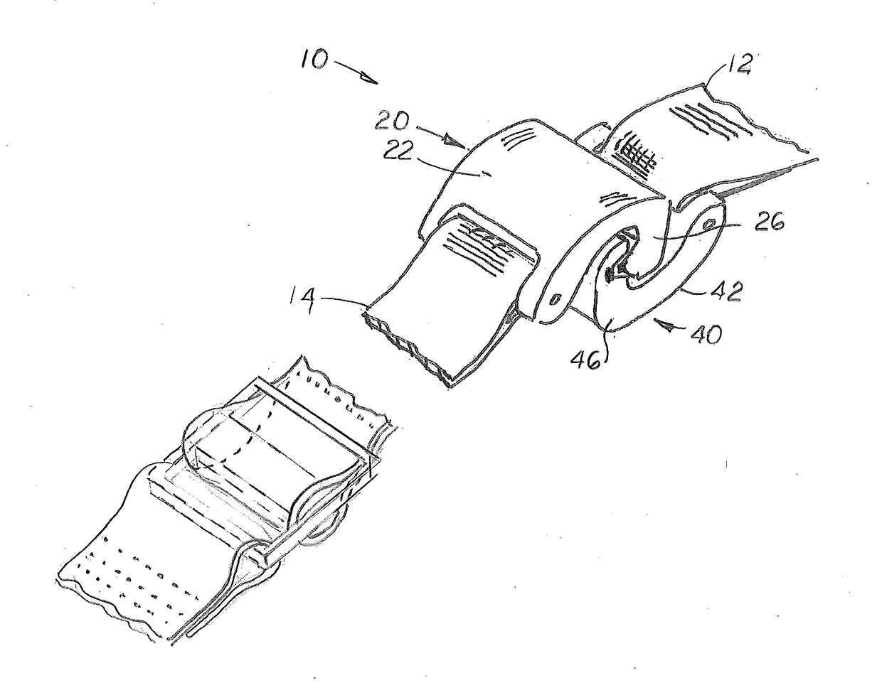
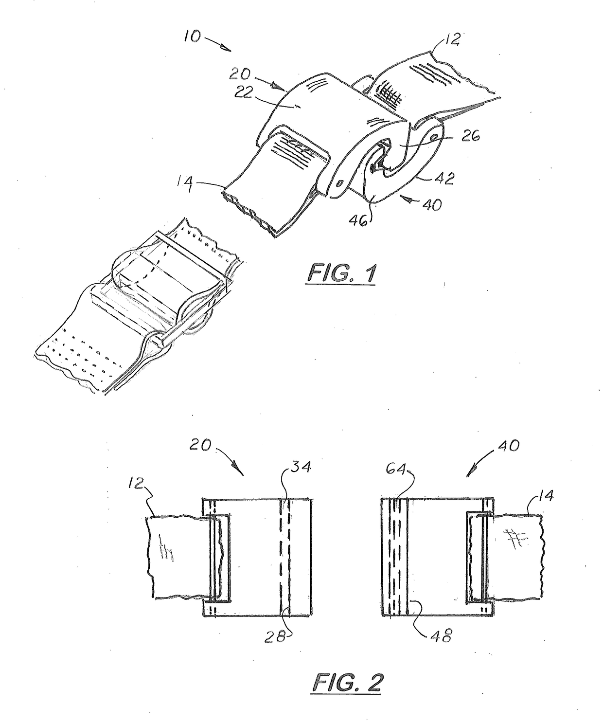
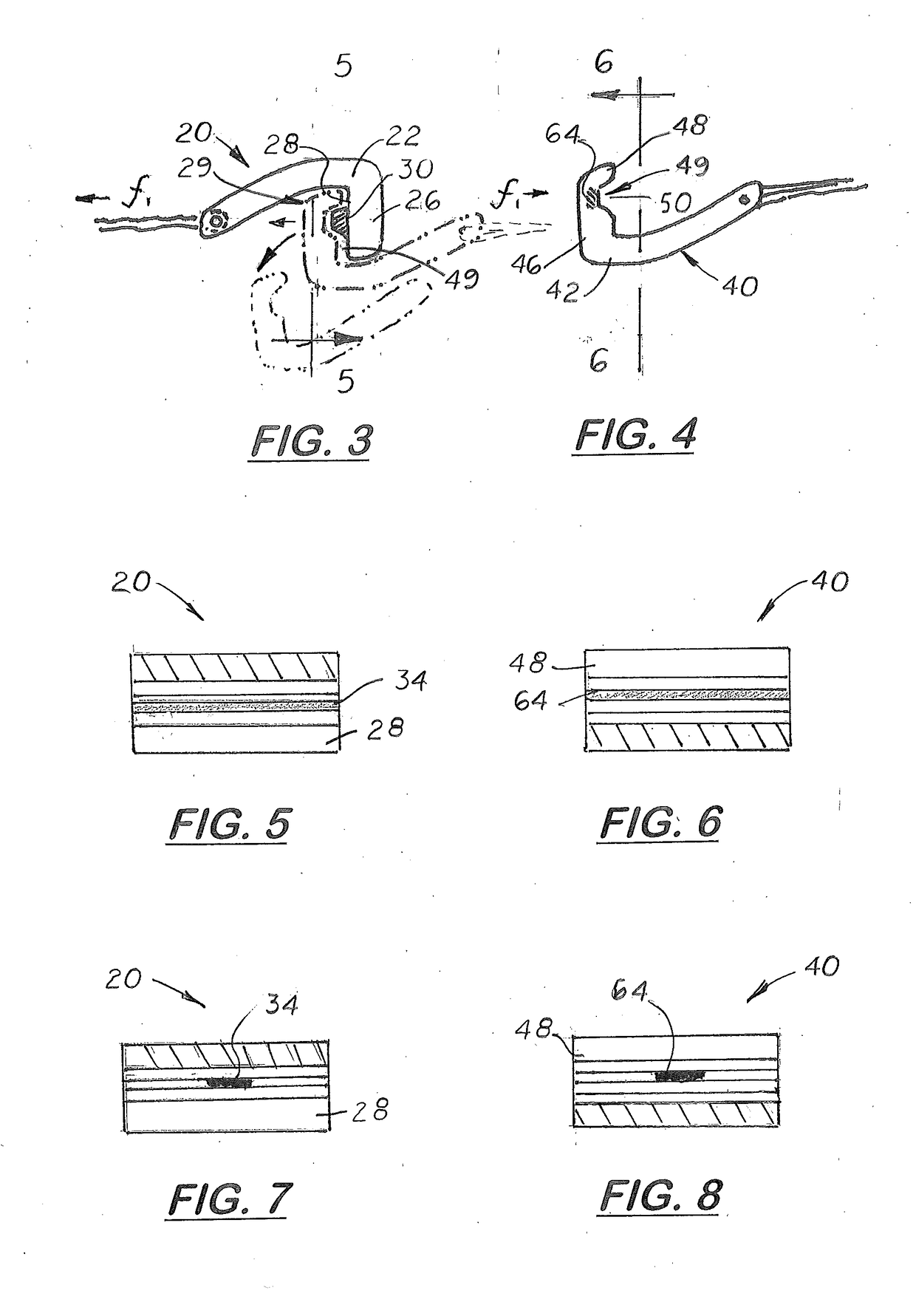
[0031]Referring to the FIGS. 1-10, there is shown a set of end connectors 20, 40 affixed to the ends 12, 14 of a single strap or two straps intended to be temporarily joined. Each end connector 20, 40 includes a rigid body 22, 42, and a lip section 26, 46, respectively, formed on its distal end. The first and second end connectors 20, 40 are attached to the ends 12, 14 of the straps so the lip sections 26, 46 are aligned in opposite direction as shown in FIGS. 1 and 3. As shown in FIGS. 3 and 4, adjacent to each lip section 26, 46 is a center void 29, 49, respectively. Formed on each lip section 26, 46 is an inward facing, transversely aligned abutment surface 28, 48, respectively. During use, the end connectors 20, 40 are longitudinally aligned and pressed together so the lip sections 26, 46 overlap until the abutment surfaces 28, 48 disposed into the voids 29, 49 formed on the adjacent end connector 20, 40 and parallel.

[0032]Formed or attached to the abutment surface 28 on the fi...


PUM


Abstract

Self-aligning, durable quick connect strap end connector system that includes a pair of identical end connectors configured to slide together and interconnect. Each end connector includes a body with a strap bar and strap slot formed on the body's proximal end. The body includes a narrow section and a lip section that extends downward and rearward. The lip section includes an abutment surface transversely aligned with the body's longitudinal axis. Located adjacent to the abutment surface is a vid area configured to receive the lip section on a second end connector longitudinally aligned with said first end connector. At least one projecting element extends from the abutment surface on said first end connector and fits into a hole formed on the abutment surface of the second end connector. Mounted on each abutment surface is at least one magnet that generate a magnetically attractive force between the two end connectors.

Description

[0001]This U.S. utility patent application is based on U.S. provisional patent application (Application No. 62 / 418,939) filed on Nov. 8, 2016.[0002]Notice is given that the following patent document contains original material subject to copyright protection. The copyright owner has no objection to the facsimile or digital download reproduction of all or part of the patent document, but otherwise reserves all copyrights.BACKGROUND OF THE INVENTION1. Field of the Invention[0003]This invention relates to belts and straps with opposite end connectors that connect to encircle, and more particular to collars, belts and straps that use end connectors that self-align easily connected and disconnected, and less susceptible to breaking or disconnection when exposed to excessive forces.2. Description of the Related Art[0004]Ideally, a dog collar should be should be sufficiently strong to withstand the pulling forces exerted by a leash or tether line, sufficiently wide so it will not slide over...

Claims


Application Information

Patent Timeline
IPC IPC(8): A44B11/28
CPCA44B11/28A44D2200/10A44D2203/00A44B11/258A01K27/005
Inventor LAMBERT, BRIAN
Owner LAMBERT BRIAN
Why Eureka
Try Eureka