Woodworking Machinery Jig and Fixture System

a technology of fixture system and jig, which is applied in the field of jigs and fixtures, can solve the problems that the current available kreg flip stop is not amenable to use for miter workpieces

Active Publication Date: 2018-07-05
DUGINSKE MARK A
View PDF13 Cites 17 Cited by
  • Summary
  • Abstract
  • Description
  • Claims
  • Application Information

AI Technical Summary

Benefits of technology

[0007]This invention provides an improved system for making improvements to and using a pocket hole jig system, such as the Kreg pocket hole jig

Problems solved by technology

Although the Kreg support stop can be used to support the bottom of the workpiece and position the board with the flip stop feature there is a problem with doing both the support and

Method used


Image

  • Woodworking Machinery Jig and Fixture System
  • Woodworking Machinery Jig and Fixture System
  • Woodworking Machinery Jig and Fixture System

Examples


Embodiment Construction

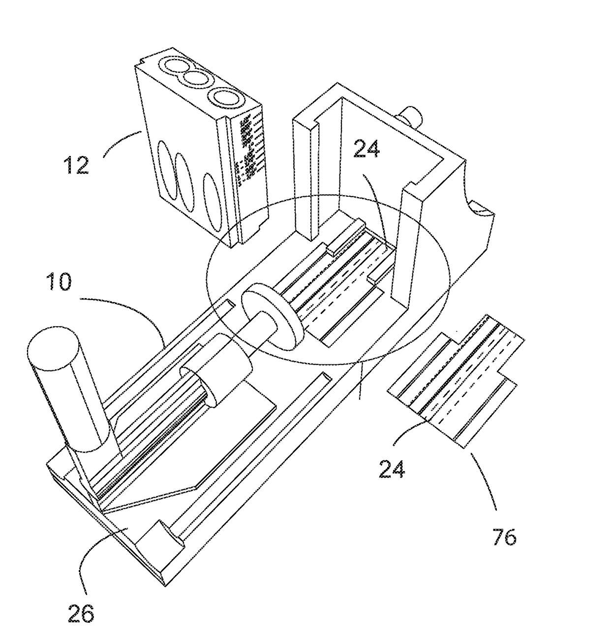
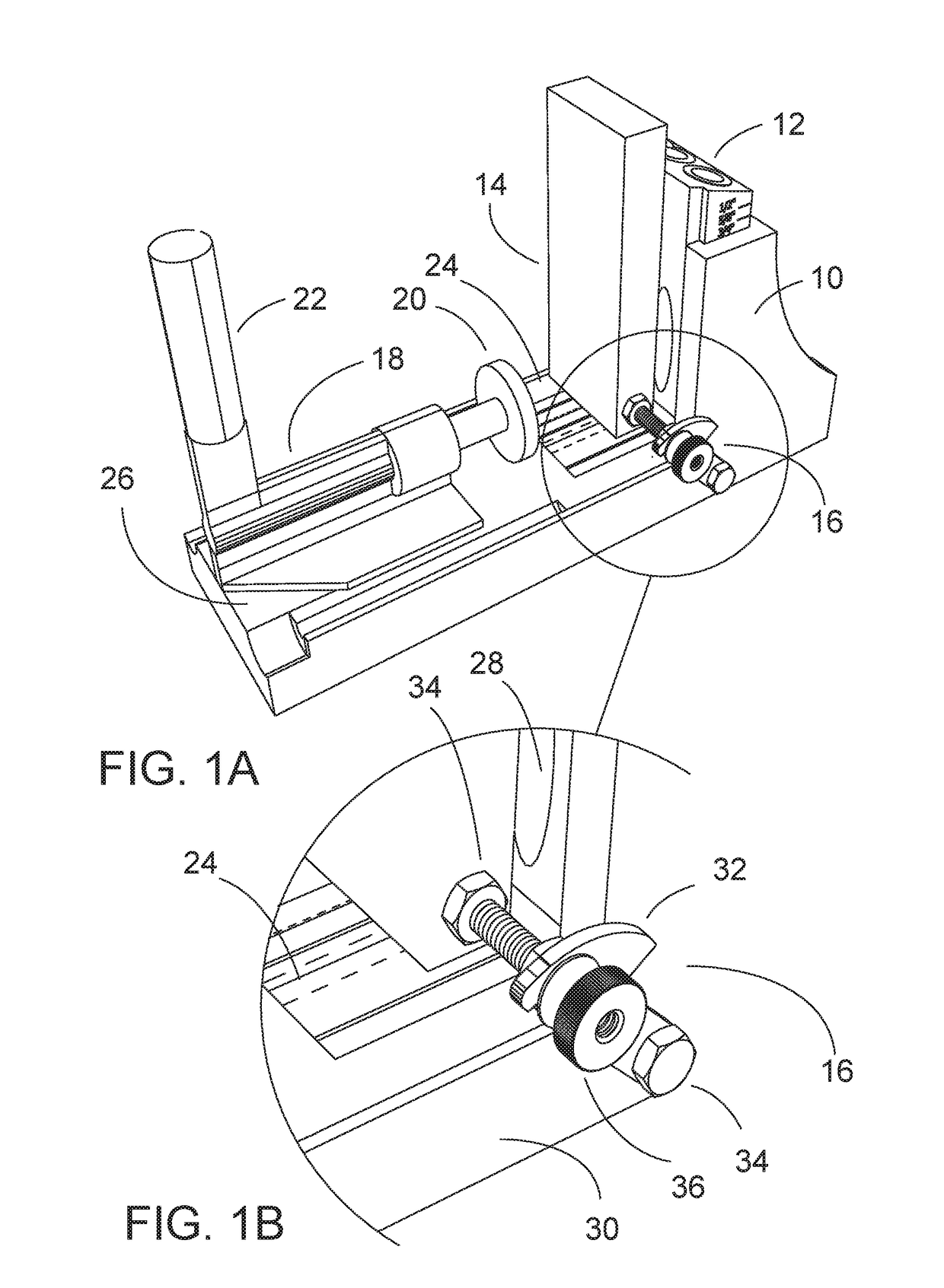
[0090]Referring to FIG. 1A a woodworking machinery jig and fixture system is disclosed incorporating a pocket hole jig 10 and a side mounted flip stop arm 16 and a decal / indicia 24 mounted on the floor 26 of the jig 10. The flip arm assembly is 16 is secured to side 30 of the pocket hole jig 10. The workpiece 14 is positioned against the stop bolt 34 for consistent measuring of the multiple work pieces. As illustrated in FIG. 1B the bolt 34 is held in place by a flip arm 32 which is bolted to the side 30 of the jig 10 with another bolt 34. A workpiece board 14 is positioned on the jig 10 for drilling in the jig 10 and is in contact with an adjustable positioning bolt 34 in the flip stop assembly 16.

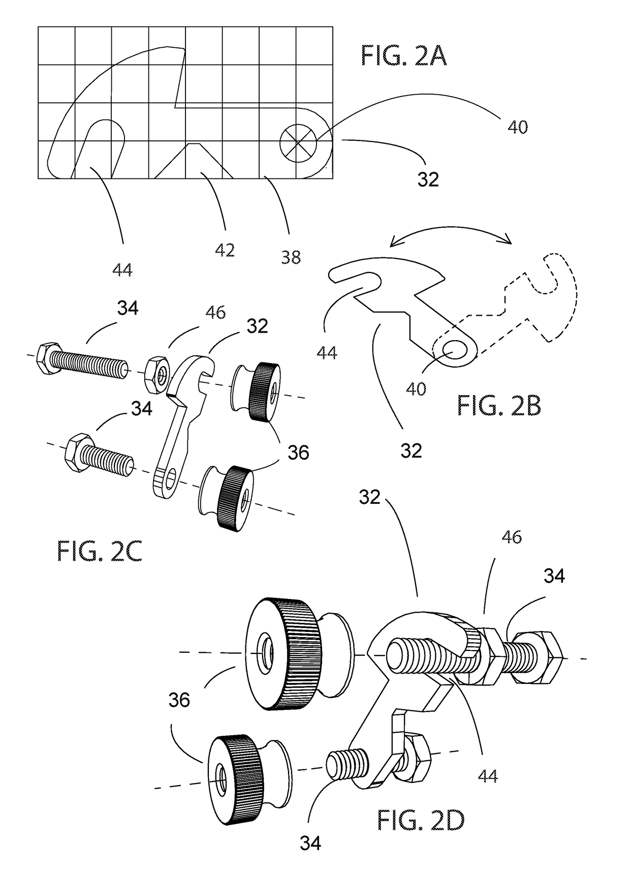
[0091]Referring to FIG. 2A and FIG. 2B the flip stop 32 is L-shaped with a hole 40 on the end of the long leg with a slot 44 on the opposite end with a V-notch 42 in the middle. FIG. 2C is an exploded view of the flip arm assembly 16 showing the adjustable bolt 34, the adjustable position...


PUM


Abstract

Jigs and fixtures for aligning, guiding, and/or holding a workpiece on woodworking machinery during a woodworking operation are described, as well as methods of making, modifying, and using jigs and fixtures.

Description

CROSS-REFERENCE TO RELATED APPLICATIONS[0001]This application claims priority from U.S. Provisional Application No. 62 / 442,761 filed Jan. 5, 2017, which is hereby incorporated by reference as if fully set forth herein.STATEMENT CONCERNING FEDERALLY SPONSORED RESEARCH OR DEVELOPMENT[0002]Not applicable.FIELD OF THE INVENTION[0003]This invention relates to jigs and fixtures for aligning, guiding, and / or holding a workpiece on woodworking machinery during a woodworking operation.BACKGROUND OF THE INVENTION[0004]Woodworking machines utilize various means of positioning or securing a workpiece as it is cut, drilled or routed. As standard equipment a pocket hole jig is usually secured to a movable plywood base. The usual approach is to add a piece of plywood (or other wood board) to the bottom of the jig, called an auxiliary table top, to provide a more stable surface to secure and control the workpiece. By adding a board that is the same thickness as the pocket hole jig to the auxiliary ...

Claims


Application Information

Patent Timeline
IPC IPC(8): B23B49/00G01B5/00B23B47/28
CPCB23B49/00G01B5/0009B23B47/28B23B2247/10B23B2260/088B23B2260/104B23B47/287
Inventor DUGINSKE, MARK A.
Owner DUGINSKE MARK A
Why Eureka
Try Eureka