Check patentability & draft patents in minutes with Patsnap Eureka AI!

Display control system, display control method, and display device

a control system and display control technology, applied in the field of display control systems, can solve the problems of user inconvenience, unnecessary images being stored, and point-by-point updating of the screen of the terminal devi

Inactive Publication Date: 2018-07-19
RICOH KK
View PDF5 Cites 1 Cited by
  • Summary
  • Abstract
  • Description
  • Claims
  • Application Information

AI Technical Summary

Benefits of technology

The present invention provides a display control system, method, and device that can detect a user's operation to update a screen and based on the content of the first screen, update another screen accordingly. The system can also determine if there is a difference in the timing of the user's operation and a previous instance, and if there is, it will not update the second screen. This helps to improve the user experience and efficiency in updating multiple screens.

Problems solved by technology

Hence, there is a possibility that eventually unnecessary images get stored.
Besides, the point-by-point updating of the screen of the terminal device might be annoying to the user.

Method used


Image

  • Display control system, display control method, and display device
  • Display control system, display control method, and display device
  • Display control system, display control method, and display device

Examples


first embodiment

[0038]Display Control System Implementable in First Embodiment

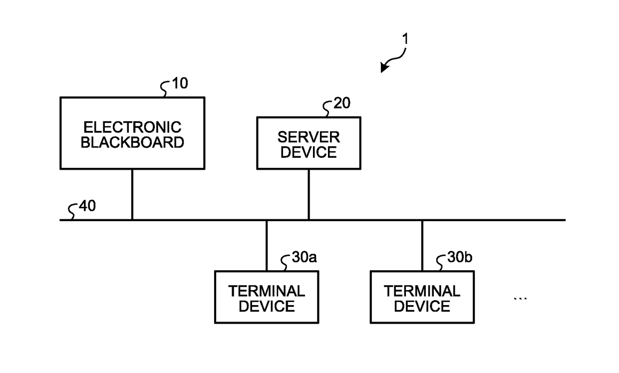
[0039]In FIG. 1 is illustrated an exemplary display control system implementable in a first embodiment. With reference to FIG. 1, a display control system 1 includes an electronic blackboard 10, a server device 20, and one or more terminal devices 30a, 30b, and so on; and all constituent elements are connected to a network 40.

[0040]The electronic blackboard 10 includes a large-sized. touch-sensitive panel in which a display device and an input device are provided in an integrated manner; and obtains, as image data, information that is input on the touch-sensitive panel (written on the blackboard) using a dedicated pen, and displays a screen according to the obtained image data. Moreover, the electronic blackboard 10 can store and output the obtained image data.

[0041]The server device 20 manages the information devices connected to the network 40, and controls the communication between the electronic blackboard 10 and the ...

second embodiment

[0170]Given below is the explanation of a second embodiment. In the first embodiment described above, the electronic blackboard 10 controls the capturing of the screen 120 thereof and controls the transmission of the captured images to the terminal device 30a. In contrast, in the second embodiment, the server device 20 controls the transmission of captured images, which are obtained in the electronic blackboard 10, to the terminal device 30a.

[0171]FIG. 19 is a functional block diagram of an example meant for explaining the functions of an electronic blackboard 10′ according to the second embodiment. With reference to FIG. 19, the same constituent elements as illustrated in FIG. 6 are referred to by the same reference numerals, and the detailed explanation of those constituent elements is not repeated. With reference to FIG. 19, as compared to the electronic blackboard 10 illustrated in FIG. 6, the electronic blackboard 10′ implementable in the second embodiment does not include the...


PUM


Abstract

According to embodiments, a display control system includes: circuitry configured to: detect a user operation meant for updating a first screen; update, in response to updating of the first screen, a second screen according to contents of the first screen; and determine, when the circuitry detects the user operation, whether or not difference between a first timing, at which the user operation is detected, and a second timing, which corresponds to timing at which the circuitry detected the user operation in previous instance, is exceeding a setting time period that is set in advance, wherein, when the circuitry determines that the difference is equal to or smaller than the setting time period, the circuitry does not update the second screen.

Description

CROSS-REFERENCE TO RELATED APPLICATIONS[0001]The present application claims priority under 35 U.S.C. § 119 to Japanese Patent. Application No. 2017-006010, filed on Jan. 17, 2017. The contents of which are incorporated herein by reference in their entirety.BACKGROUND OF THE INVENTION1. Field of the Invention[0002]The present invention relates to a display control system, a display control method, and a display device.2. Description of the Related Art[0003]In recent years, terminal devices such as tablet computers and electronic blackboards that function as digital screen display media have become popular, and there has been an increase in the case examples in which such terminal devices are introduced in business enterprises and schools. Moreover, with the use of such terminal devices, storing a variety of information and application of the stored information is being considered. For example, storing and utilizing the screens displayed on an electronic blackboard is being considered...

Claims


Application Information

Patent Timeline
IPC IPC(8): G06F3/041G06F3/0354
CPCG06F3/0412G06F3/03545G06F3/0416G06F3/04883G06F2203/04807
Inventor KAREI, YUTO
Owner RICOH KK
Features
  • R&D
  • Intellectual Property
  • Life Sciences
  • Materials
  • Tech Scout
  • Unparalleled Data Quality
  • Higher Quality Content
  • 60% Fewer Hallucinations
Learn More