

Longitudinal differential interferometric confocal microscopy
- Summary
- Abstract
- Description
- Claims
- Application Information
AI Technical Summary
Benefits of technology
Problems solved by technology
Method used
Image

Examples
first embodiment
[0048]There will be a restriction on the duration or “pulse width” of a beam pulse τp1 produced by source 18 as a result of the continuous scanning mode used in the third variant of the Pulse width τp1 will be a parameter that in part controls the limiting value for spatial resolution in the direction of a scan to a lower bound of
τp1V, (1)
where V is the scan speed. For example, with a value of τp1=50 nsec and a scan speed of V=0.20 m / sec, the limiting value of the spatial resolution τp1V in the direction of scan will be
τp1V=10 nm. (2)
[0049]Pulse width τp1 will also determine the minimum frequency difference that can be used in the bi- and quad-homodyne detection methods. In order that there be no contributions to the electrical interference signals from interference between fields of conjugated quadratures, the minimum frequency spacing Δfmin is expressed as
[0050]Δfmin>>1τp1.(3)
For an example of τp1=50 nsec, 1 / τp1=20 MHz.
[0051]For certain embodiments, the frequencies of input b...
second embodiment
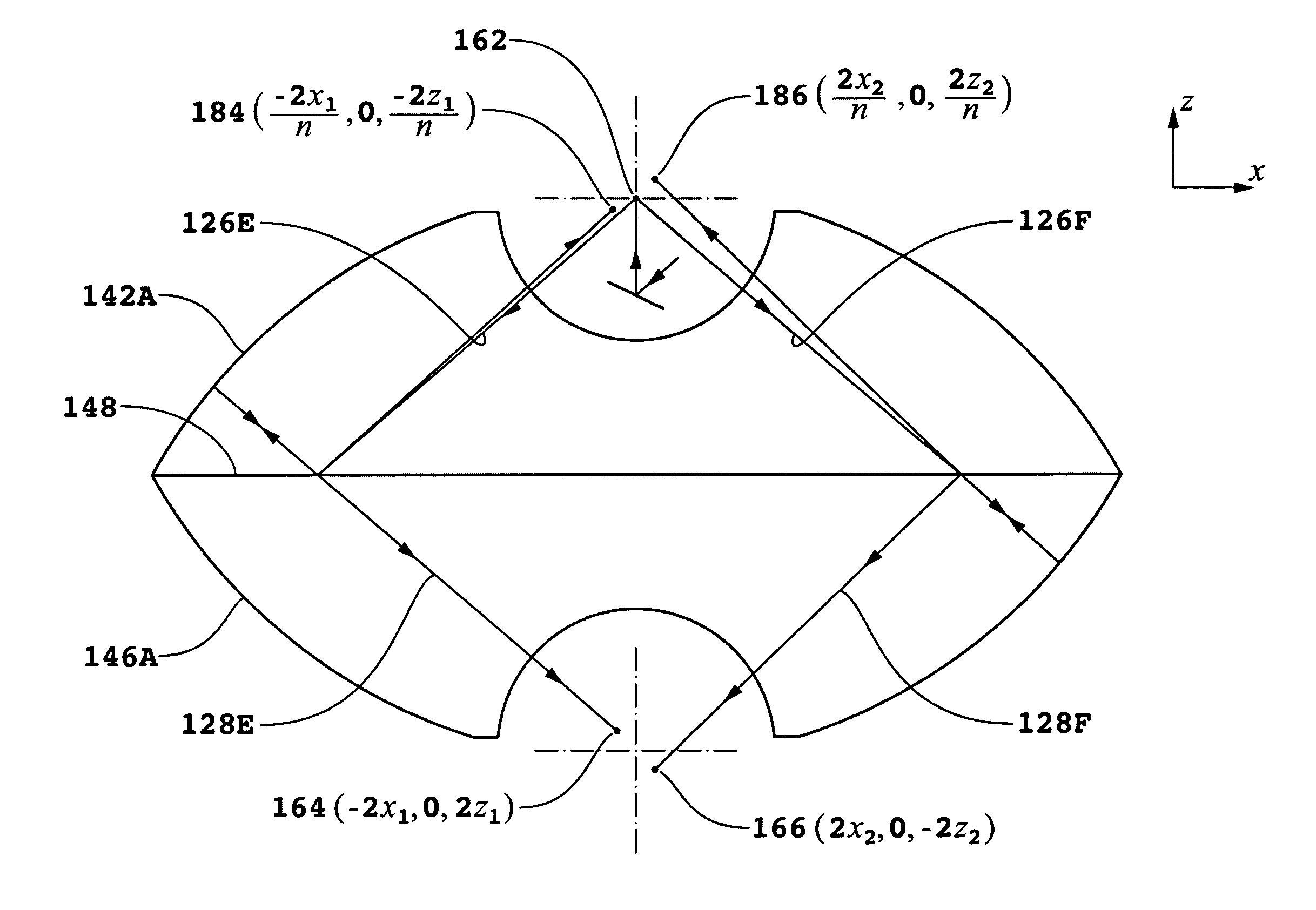
[0159]One important application of the second embodiment is the determination of differences in height of a first region comprising a feature or an artifact relative to a neighboring second region used as a reference region. The first and second regions would have heights corresponding to h1 and h2, respectively. The factors (h1+h2) / 2 and (h1−h2) represent the average height and the difference in heights of the two regions on the surface of substrate 60 corresponding to beams forming spots 190 and 192. The coefficients of h1 and h2 in Equation (36) and coefficients of (h1+h2) / 2 and (h1−h2) in Equation (37) can be independently measured by measuring V2 (h1,z1, h2, z2,χ=π) with substrate 60 stationary in the x-y plane and with transducers 86A and 86B introducing a scan in z to obtain measurements at at least two different positions (thereby changing h1 and h2 and causing the average (h1+h2) / 2 to change but keeping the difference (h1−h2) the same) and scans in orientation of substrate ...
PUM
 Abstract
Description
Claims
Application Information