Apparatus and Method for Driving and Measuring a MEMS Mirror System

Active Publication Date: 2015-11-05
TRILITE TECH
View PDF1 Cites 7 Cited by
  • Summary
  • Abstract
  • Description
  • Claims
  • Application Information

AI Technical Summary

Benefits of technology

[0010]The invention allows to impart or force any desired movement pattern onto the minor, e.g. a triangular or sawtooth pattern to deflect a laser beam linearly. At the same time, the resulting pulse modulated drive signal for the minor features intervals which can be used to measure the forced movement of the mirror. This measurement is done purely electrically without the need for an external optical measurement of the deflected laser beam or separate sensors inside the MEMS minor system just by using the existing two terminals of the driving coil at which the modulated pulse signal is input. It is thus possible to obtain information on the actual movement caused by a drive signal of arbitrary form.
[0011]The invention is especially useful in displays with huge numbers of individual MEMS minor systems as pixels in an array since each MEMS mirror syste

Problems solved by technology

However, the movement of the resonating minor is restricted to a sinusoidal pattern of a varying, non-linear angular velocity, making it unsuitable for a series of applications.
Since this resonance frequency is subject to the ph

Method used


Image

  • Apparatus and Method for Driving and Measuring a MEMS Mirror System
  • Apparatus and Method for Driving and Measuring a MEMS Mirror System
  • Apparatus and Method for Driving and Measuring a MEMS Mirror System

Examples


first embodiment

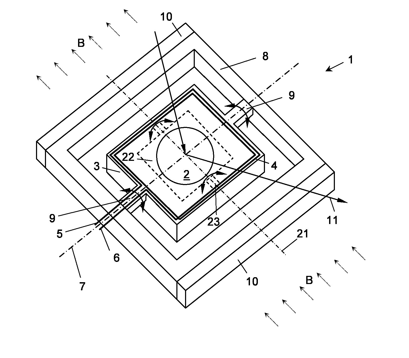
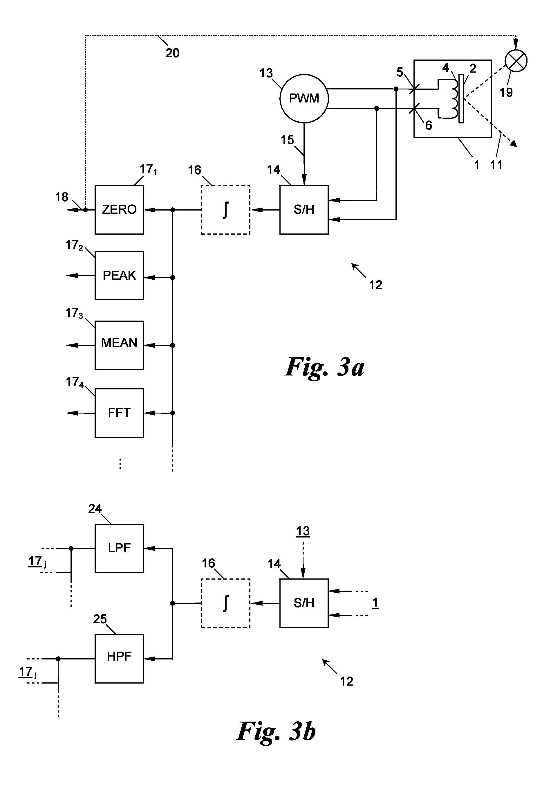
[0045]a signal analysis unit 17j is, for example, a “no operation” detector 171 which checks whether the mirror 2 is moving at all by detecting the angular velocity va or angular position pa to continuously be substantially zero over an observation time span, e.g. of one or more cycles of the modulation frequency fm. In this way a failure or “freezing” of the minor movement can be detected and a subsequent alarm can be set off on an output 18 of the detector 171. Alternatively a light source 19 of the laser beam 11 can be switched off via a control path 20 to implement eye-safety standards for viewers of the MEMS mirror system 1.

[0046]The signal analysis unit 17j can further be embodied as a peak detection device 172 detecting a peak value, e.g. the global minimum and maximum values of a series of signal values svk or integrated signal values isvk, e.g. to determine the maximum amplitude or a highest angular velocity va of the mirror movement.

third embodiment

[0047]the signal analysis unit 17j is shown as a mean value detector 173, e.g. determining a mean value of the angular velocity va or angular position pa over a gliding time window. For example, peak and mean values can be used to further evaluate a gradual deviation from reference values, e.g. indicating a decalibration or ageing of the MEMS minor system 1 or its driving circuitry.

[0048]A fourth exemplary embodiment of the signal analysis unit 17j is a frequency analyzer 174, by means of which certain frequency components of the angular velocity va and / or angular position pa, e.g. corresponding to parasitic or interfering frequencies, can be discovered, which may be caused by unwanted mechanical vibrations of the system 1.

[0049]FIG. 5 shows an example of measurements performed on the MEMS mirror system 1 with the apparatus 12 and method described herein. The modulation frequency fm was set at 55 Hz and the PWM pulse frequency fp at 453 kHz, the MEMS mirror system 1 exhibiting a res...


PUM


Abstract

The present invention relates to an apparatus for driving and measuring a MEMS minor system, the MEMS minor system having a mirror pivotable around an axis by a driving coil and exhibiting a resonance frequency, having a pulse generator and a measuring unit, each electrically connected to the coil. The pulse generator is preferably configured to feed a modulated pulse signal, comprised of pulses separated by intervals and having a modulation frequency different from the resonance frequency, to the coil. The measuring unit is preferably configured to measure a value of a signal output by the coil during an interval of the modulated pulse signal. In a further aspect of the invention a method is provided for driving and measuring the MEMS mirror system.

Description

CROSS-REFERENCE TO RELATED APPLICATION[0001]This application claims priority to European Patent Application No. 14 166 714.7, filed on Apr. 30, 2014, the entirety of which is incorporated by reference herein.BACKGROUND[0002]The present invention relates to an apparatus for driving and measuring a MEMS mirror system, the MEMS mirror system having a minor pivotable around an axis by a driving coil and exhibiting a resonance frequency. The invention further relates to a method for driving and measuring said MEMS minor system.[0003]Mirror systems in the form of micro-electro-mechanical systems (MEMS) are known in the art as devices capable of pivoting a minor around an axis at a high frequency, e.g. in order to deflect a laser beam in a specific direction. This can be used for projectors which project light along a viewing zone, e.g. with a rate of a few thousand cycles per second.[0004]One type of state of the art MEMS minor systems, e.g. as disclosed in EP 1 515 424 A2, drives the min...

Claims


Application Information

Patent Timeline
IPC IPC(8): G02B26/08
CPCG02B26/0833G02B26/085
Inventor HAMBECK, CHRISTIANREITTERER, JOERGFIDLER, FRANZ
Owner TRILITE TECH
Why Eureka
Try Eureka