Method for Policy and Charging Rules Function (PCRF) Informing Centralized Deployment Functional Architecture (BPCF) of User Equipment Access Information

a technology of user equipment and functional architecture, applied in the field of communication, can solve problems such as the inability of the bpcf to perform qos guarantee on data

Active Publication Date: 2013-04-25
ZTE CORP
View PDF3 Cites 7 Cited by
  • Summary
  • Abstract
  • Description
  • Claims
  • Application Information

AI Technical Summary

Benefits of technology

[0032]In conclusion, the present invention provides a system and method for performing QoS control on the UE, which can implement that the BPCF obtains the tunnel information of the UE and performs QoS control.

Problems solved by technology

In this case, the trusted access system of the fixed network operators can't know tunnel information of the UE, and thus the BPCF is unable to perform QoS guarantee to the data, passing through the fixed network access system, of the UE.

Method used


Image

  • Method for Policy and Charging Rules Function (PCRF) Informing Centralized Deployment Functional Architecture (BPCF) of User Equipment Access Information
  • Method for Policy and Charging Rules Function (PCRF) Informing Centralized Deployment Functional Architecture (BPCF) of User Equipment Access Information
  • Method for Policy and Charging Rules Function (PCRF) Informing Centralized Deployment Functional Architecture (BPCF) of User Equipment Access Information

Examples


example 1

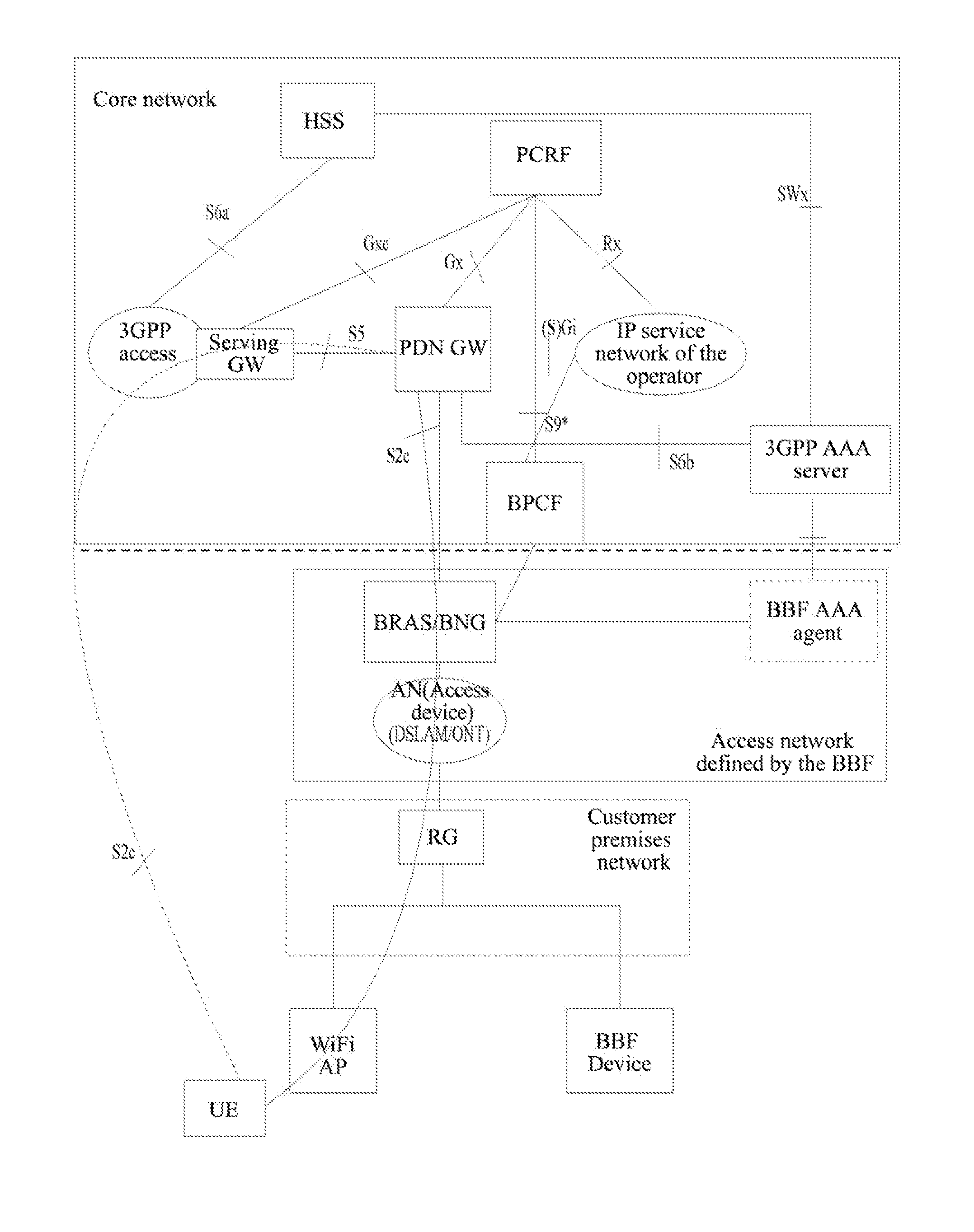
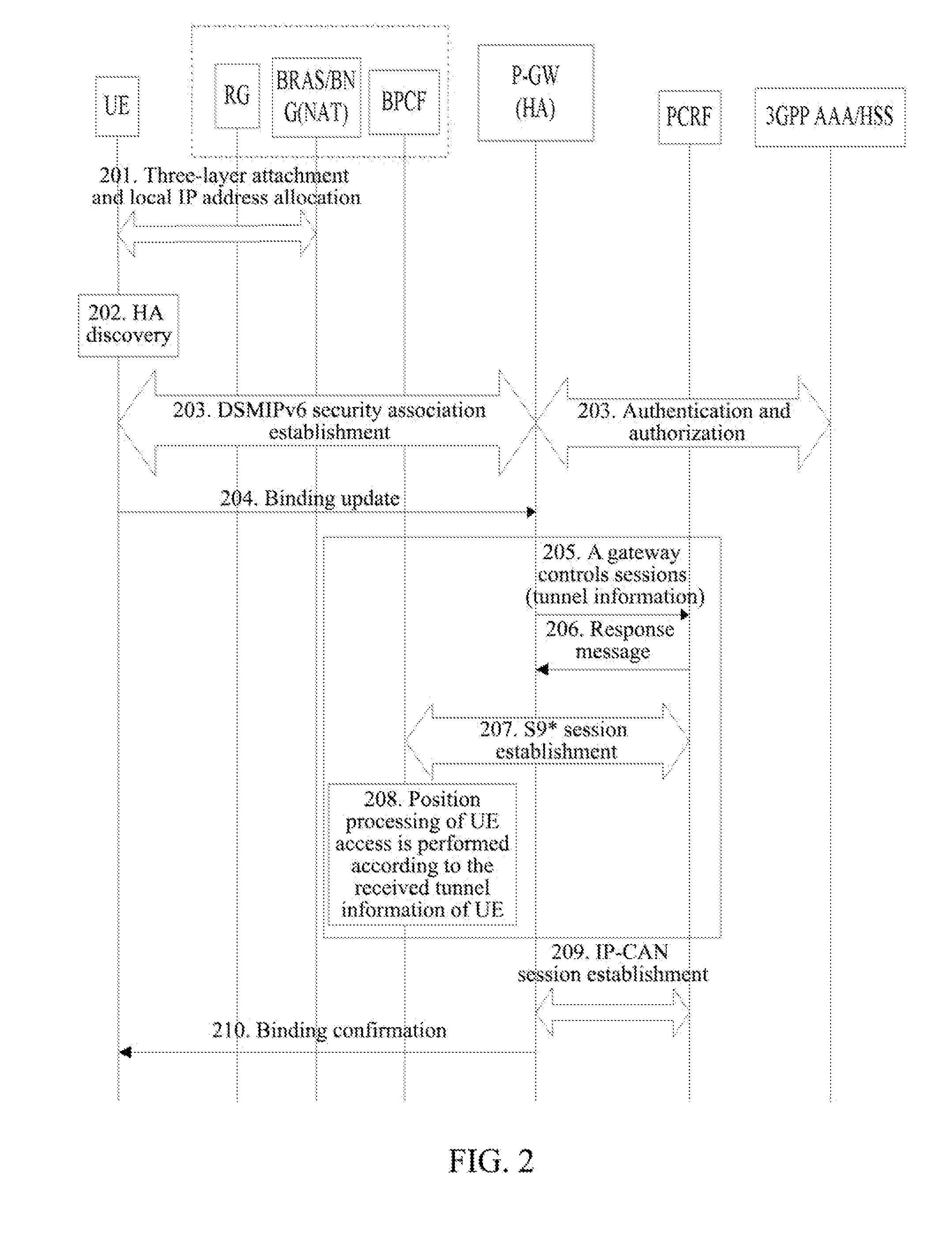
[0049]A UE accessing a BBF customer premises network and an access network through a WiFi AP based on an interface S2c to initially attach to a wireless access network is as shown in FIG. 2. A local IP address of the UE is allocated by a BRAS, and in the process of the UE performing initial attachment based on DSMIPv6, a PCRF informs a BPCF of access information of the UE. In order to save address space, what the BRAS allocates to the UE is a private IP address, NAT will be performed on an IP packet in the BRAS (the local IP address of the UE is seen from a perspective of network side, and if what the BRAS allocates to the UE is the private IP address, the local IP address refers to a public IP address translated from the private IP address). Here, it is noted that there is no limitation to the sequence of the messages reaching the HA in steps 205˜208 and in step 204, that is, step 205 can be initiated as long as a PDN GW acquires access information of the UE needed. The specific fl...

example 2

[0066]A UE performing handover from a 3GPP access network to a BBF access system is as shown in FIG. 3. A local IP address of the UE is allocated by an RG, in order to save address space, what the RG allocates to the UE is a private IP address, and NAT will be performed on an IP packet in the RG (the local IP address of the UE is seen from a perspective of network side, and if what the RG allocates to the UE is the private IP address, the local IP address refers to a public IP address translated from the private IP address). Here, it is noted that there is no limitation to the sequence of the messages reaching the HA in steps 306˜309 and in step 310, that is, step 306 can be initiated as long as a PDN GW acquires access information of the UE needed. The specific flow steps are described as follows.

[0067]In step 301, the UE establishes an EPS bearer connection through a 3GPP access system.

[0068]In step 302, the UE discovers the BBF access system and prepares to switch the current con...


PUM


Abstract

A system and method for performing quality of service control on a user equipment are provided in the present invention. The method includes: after establishing an Internet Key Exchange version 2 (IKEv2) security association between the user equipment and a packet data network gateway to establish an Internet Protocol Security (IPSec) tunnel, the packet data network gateway sending IPSec tunnel information to a Policy and Charging Rules Function (PCRF), the PCRF then sending the IPSec tunnel information to a Broadband Policy Control Function (BPCF), and the BPCF performing quality of service control on services of the user equipment according to the received IPSec tunnel information. With the technical scheme of the present invention, it enables the BPCF to acquire tunnel information of the user equipment and then perform quality of service control on the user equipment.

Description

TECHNICAL FIELD[0001]The present invention relates to the field of communication, and specifically, to a system and method for performing service quality control on a user equipment.BACKGROUND OF THE RELATED ART[0002]In the 3rd Generation Partnership Project (3GPP) Evolved Packet System (EPS), a diagram of network architecture of the EPS in a non-roaming scenario as shown in FIG. 1 is composed of an Evolved Universal Terrestrial Radio Access Network (E-UTRAN), a Mobility Management Entity (MME), a Serving Gateway (S-GW), a Packet Data Network Gateway (P-GW or PDN GW), a Home Subscriber Server (HSS), a Policy and Charging Rules Function (PCRF) entity and other support nodes.[0003]An Application Function (AF) entity provides access points of service applications, and it is required to perform dynamic policy control on network resources used by these service applications. When the parameter negotiation is performed in a service plane, an AF transfers relevant service information to the...

Claims


Application Information

Patent Timeline
Patent Type & Authority Applications(United States)
IPC IPC(8): H04L29/08
CPCH04L12/2856H04L41/5032H04L63/164H04M15/66H04W4/24H04L41/0869H04L61/2514H04W76/022H04L67/14H04L41/5054H04L41/0896H04L61/2592H04W76/12H04L41/0894
Inventor ZHOU, XINGYUEZHOU, XIAOYUN
Owner ZTE CORP
Why Eureka
Try Eureka