Position detection device

Inactive Publication Date: 2018-08-02
ALPS ALPINE CO LTD
View PDF6 Cites 3 Cited by
  • Summary
  • Abstract
  • Description
  • Claims
  • Application Information

AI Technical Summary

Benefits of technology

[0016]In an aspect of the present invention, attention is focused on differences in demagnetizing factor for the magnetic flux density of a magnetic field generated by a magnet due to a temperature change between a direction perpendicular to a magnetized surface of the magnet and a direction parallel to the magnetized surface, and the magnetized surface, that is, a surface facing a detection unit, has a shape such that both ends thereof in a direction extending along a relative movem

Problems solved by technology

In an actual position detection device, however, a problem arises in that, in a high-temperature environment, the value of the arc tangent computed on the basis of the output

Method used


Image

  • Position detection device
  • Position detection device
  • Position detection device

Examples


Example

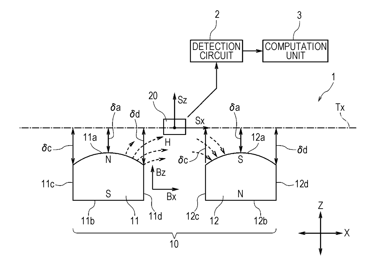
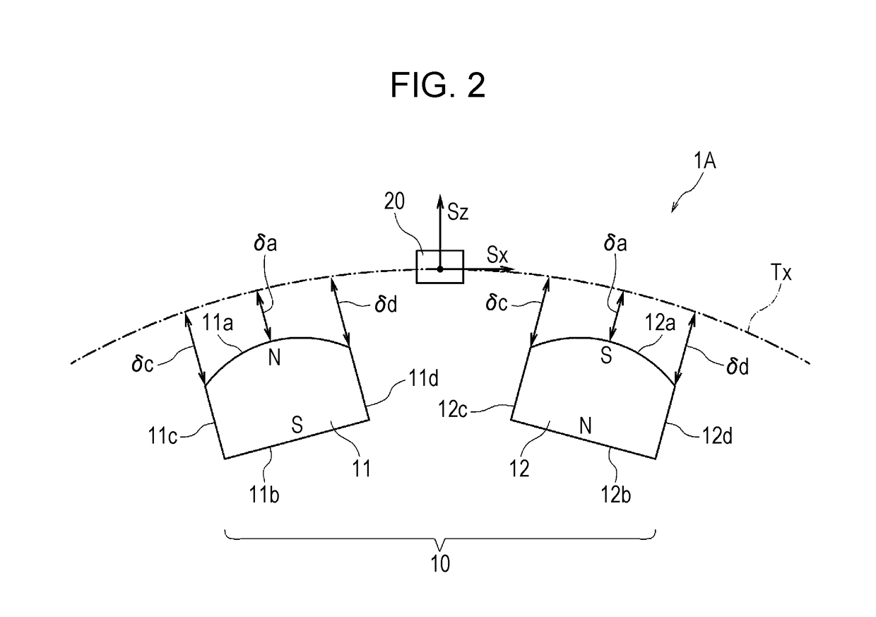
[0056]FIG. 4A illustrates Example 1, in which a single magnet 11 faces the relative movement trajectory Tx of the detection unit 20. FIG. 4B illustrates Example 2, in which two magnets 11 and 12 face the relative movement trajectory Tx of the detection unit 20. FIG. 4C illustrates Example 3, in which three magnets 11, 12, and 13 face the relative movement trajectory Tx of the detection unit 20.

[0057]The magnets 11, 12, and 13 have facing surfaces 11a, 12a, and 13a that are projecting curved surfaces having curvatures in a direction extending along the movement trajectory Tx, with their radii of curvature being indicated by R.

Example

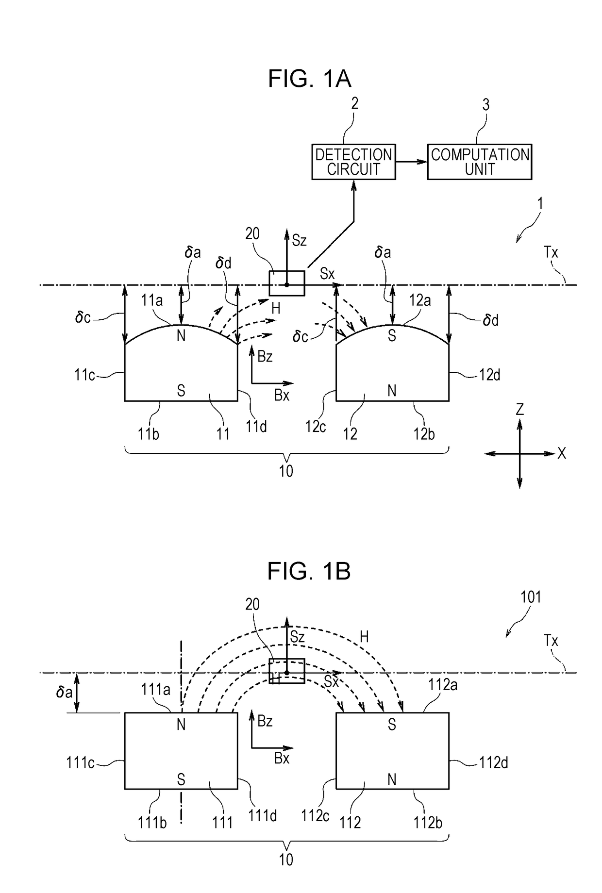
[0058]FIG. 5A illustrates Comparative Example 1, in which a single magnet 111 faces the relative movement trajectory Tx of the detection unit 20. FIG. 5B illustrates Comparative Example 2, in which two magnets 111 and 112 face the relative movement trajectory Tx of the detection unit 20. FIG. 5C illustrates Comparative Example 3, in which three magnets 111, 112, and 113 face the relative movement trajectory Tx of the detection unit 20.

[0059]The magnets 111, 112, and 113 have facing surfaces 111a, 112a, and 113a that are all flat surfaces.

[0060]The magnets 11, 12, and 13 in Examples and the magnets 111, 112, and 113 in Comparative Examples are each a rare-earth based (Nd—Fe—B based) injection molded magnet.

[0061]The magnets 11, 12, and 13 in Examples and the magnets 111, 112, and 113 in Comparative Examples each have dimensions such that a height Hm is 6 mm, a length L in a direction extending along the movement trajectory Tx is 9 mm, and a width W in a direction perpendicular to the...

Example

[0062]In Example 2 in FIG. 4B and Comparative Example 2 in FIG. 5B, an inter-magnet distance S1 is 17 mm, and in Example 3 in FIG. 4C and Comparative Example 3 in FIG. 5C, an inter-magnet distance S2 is 18 mm.

[0063]FIGS. 6A, 6B, and 6C illustrate the moving position of the detection unit 20 and the linearity error for outputs of the detection unit 20 in the respective Examples. FIGS. 7A, 7B, and 7C illustrate the moving position of the detection unit 20 and the linearity error for outputs of the detection unit 20 in the respective Comparative Examples.

[0064]In FIGS. 6A to 6C and FIGS. 7A to 7C, the horizontal axis represents the relative positions of each magnet and the detection unit 20 along the movement trajectory Tx.

[0065]FIG. 6A illustrates measurement results of Example 1, and the origin “0” of the horizontal axis indicates that, as illustrated in FIG. 4A, the detection unit 20 is positioned to face the center of the magnet 11. FIG. 6B illustrates measurement results of Exampl...


PUM


Abstract

A movement unit is provided with a first magnet and a second magnet. A detection unit includes a first magnetic sensor having an axis of sensitivity and a second magnetic sensor having an axis of sensitivity different from the axis of sensitivity of the first magnetic sensor. The movement unit and the detection unit are movable relatively to each other along a movement trajectory. The first and second magnets have facing surfaces, each of which is a projecting curved surface having a shape such that both ends thereof are positioned farther away from the movement trajectory than a center portion thereof. This shape can suppress the linearity error for measured values when the first and second magnets are demagnetized in a high-temperature environment.

Description

CLAIM OF PRIORITY[0001]This application is a Continuation of International Application No. PCT / JP2016 / 074941 filed on Aug. 26, 2016, which claims benefit of Japanese Patent Application No. 2015-211556 filed on Oct. 28, 2015. The entire contents of each application noted above are hereby incorporated by reference.BACKGROUND OF THE INVENTION1. Field of the Invention[0002]The present invention relates to a position detection device that detects the relative positions and movement of a magnet and a detection unit having a magnetic sensor.2. Description of the Related Art[0003]Japanese Registered Utility Model No. 3191531 describes an invention relating to a position detection device.[0004]The position detection device has a case accommodating a holder that moves to advance and retreat, and the holder is provided with two magnets that are arranged side by side in a moving direction. A detection unit is fixed to the case. The detection unit is provided with two magnetoresistive elements f...

Claims


Application Information

Patent Timeline
IPC IPC(8): G01B7/00G01R33/09G01D5/12
CPCG01B7/003G01R33/09G01D5/12G01D3/036G01D5/145G01B5/0014G01R33/02
Inventor YASUDA, YUKIKOTOKUNAGA, ICHIROSAITO, TAKU
Owner ALPS ALPINE CO LTD
Why Eureka
Try Eureka