
Solenoid valve for brake system

a solenoid valve and brake system technology, applied in the direction of valve details, valve arrangement, braking system, etc., can solve the problems of tire slippage on the road surface, and achieve the effects of reducing gap, improving operational durability, and stably moving

Active Publication Date: 2014-09-16
HL MANDO CORP
View PDF24 Cites 4 Cited by
  • Summary
  • Abstract
  • Description
  • Claims
  • Application Information

AI Technical Summary

Benefits of technology

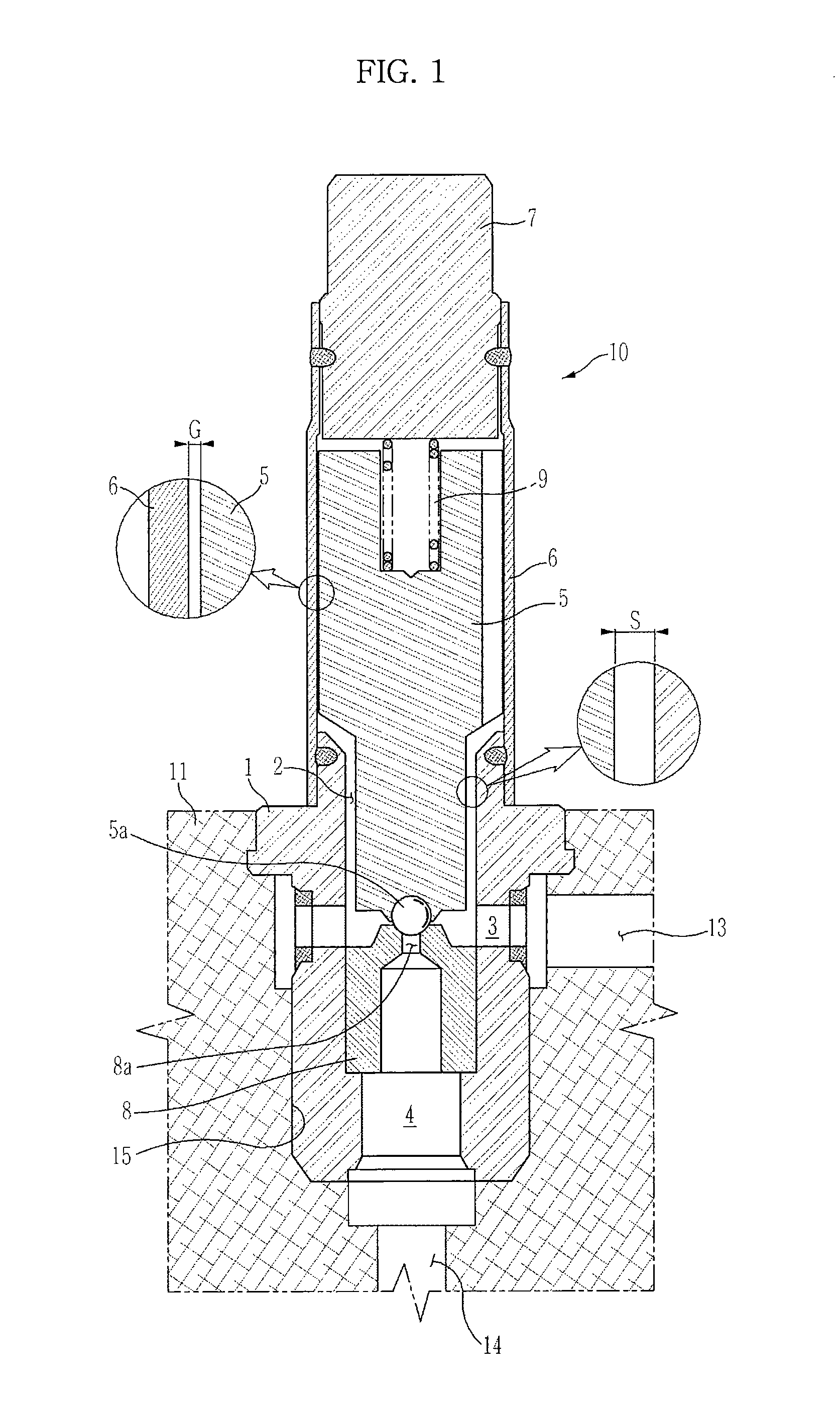
The present invention provides a solenoid valve for a bracket system that has a reduced gap between the armature and seat housing to prevent shaking and improve durability and responsiveness. Another aspect of the invention is to reduce friction between the armature and seat housing to enhance the responsiveness of the solenoid valve.

Problems solved by technology

Here, if braking force applied to the tires exceeds static frictional force between a road surface and the tires, tire slippage occurs on the road surface.

Method used


Image

  • Solenoid valve for brake system
  • Solenoid valve for brake system
  • Solenoid valve for brake system

Examples


Embodiment Construction

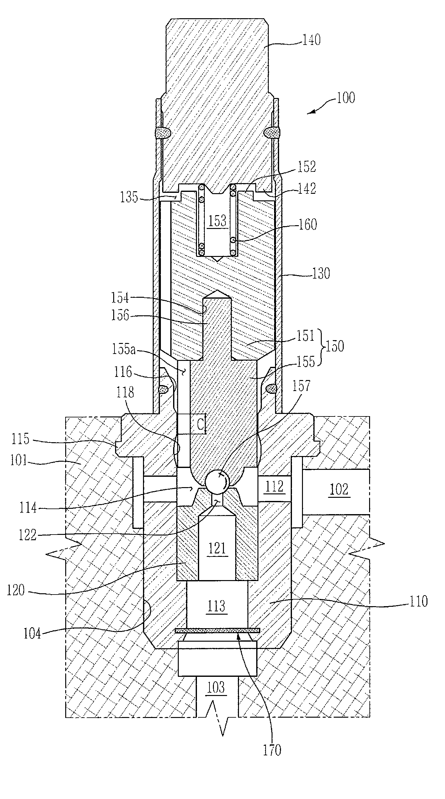
[0036]Reference will now be made in detail to the embodiments of the present invention, examples of which are illustrated in the accompanying drawings, wherein like reference numerals refer to like elements throughout. It should be understood that the terms used in the specification and appended claims should not be construed as limited to general and dictionary meanings but should be construed based on the meanings and concepts according to the spirit of the present invention on the basis of the principle that the inventor is permitted to define appropriate terms for best explanation. The embodiments described in the specification and shown in the drawings are purely illustrative and are not intended to represent all aspects of the invention, such that various equivalents and modifications may be made without departing from the spirit of the invention.

[0037]FIG. 3 is a sectional view illustrating a solenoid valve for a brake system in accordance with an embodiment of the present in...


PUM


Abstract

Disclosed is a solenoid valve for a brake system which improves an assembly structure of components configuring the valve to enhance durability and control performance of the valve.The solenoid valve for a brake system includes a seat housing installed at a bore of a modulator block and provided with a through hole formed therethrough, a valve seat installed at the through hole of the seat housing and provided with an orifice, a sleeve provided with a hollow and connected to the seat housing, a magnetic core, an armature installed at the sleeve, and a return spring installed in the sleeve, wherein the armature includes an upper armature formed of a magnetic material, and a lower armature formed of a non-magnetic material, wherein the through hole of the seat housing is provided with a guide region having a diameter corresponding to an outer diameter of the lower armature.

Description

CROSS-REFERENCE TO RELATED APPLICATION(S)[0001]This application claims the benefit of Korean Patent Application No. P2011-113119, filed on Nov. 2, 2011 in the Korean Intellectual Property Office, the disclosure of which is incorporated herein by reference.BACKGROUND[0002]1. Field[0003]Embodiments of the present invention relate to a solenoid valve for a brake system which improves an assembly structure of components configuring the valve to enhance durability and control performance of the valve.[0004]2. Description of the Related Art[0005]In general, a hydraulic brake of a vehicle performs braking operation by applying hydraulic pressure to a master cylinder through operation of a brake pedal. Here, if braking force applied to the tires exceeds static frictional force between a road surface and the tires, tire slippage occurs on the road surface.[0006]However, a coefficient of kinetic friction is smaller than a coefficient of static friction, and thus in order to achieve optimal br...

Claims


Application Information

Patent Timeline
Patent Type & Authority Patents(United States)
IPC IPC(8): F16K31/02B60T8/36F16K31/06
CPCB60T8/363F16K31/0693F16K31/0665B60T8/36F16K31/06
Inventor KIM, HYUN JUNYANG, I JINKIM, YONG KAPRYU, DONG YOPARK, JONG YOUNG
Owner HL MANDO CORP
Learn More