Flat Lamp

Active Publication Date: 2018-08-09
KUNSHAN CHENGTAI ELECTRIC
View PDF14 Cites 0 Cited by
  • Summary
  • Abstract
  • Description
  • Claims
  • Application Information

AI Technical Summary

Benefits of technology

The present invention is about a flat lamp that uses a plastic buffer layer for anti-deformation, and a diffusion layer for changing color and protecting the light guide layer from scratches. The flat lamp also has the advantages of uniform light emission, low cost, and easy implementation. The invention also includes a method for producing wedge-shaped light guide plates with different inclined plane angles and thicknesses, which reduces production cost and allows for continuous production, stable production process, and high efficiency.

Problems solved by technology

The more common applications, such as LED lamp panels, that is, a plurality of LED lamp caps are arranged in an array in a lampshade, and the corresponding drive circuit is provided in the lampshade, the structure is simple and practical, but LED lamp panels are comparatively dazzling and the uniformity of the emitted light is poor (uniformity<70%) because LED lamp panels use direct type light source.
The kind of LED flat lamps emit light and generate heat during operation, and the LED flat lamp is easily deformed and damaged based on the principle of thermal expansion and cold contraction if the generated heat cannot be released in time, which shortens the service life.
1. The diffusion plate uses the same material, such as: PS (polystyrene)\PMMA (polymethyl methacrylate)\PC(polycarbonate)\PET(polyethylene terephthalate)\PP(poly Propylene\PE(polyethylene), etc., but not limited to these materials, PS\PMMA\PC\PET has good flatness but is a hard material, and PP / PE material is soft, deformable and not flat enough thereof. The conventional light guide layer is also made of the same plastic material, such as PS\PMMA\PC\PET, but not limited to these materials. In the design of the conventional flat lamp and surface light source product, the light guide layer and the diffusion layer are tightly attached to each other. If the light guide layer and the diffusion layer are made of the same material, the light-emitting surface of the light guide layer gets easily damaged, which cause the light guide layer to be scrapped. Therefore, the diffusion layer and the light guide layer of the flat lamp and the surface light source product in the prior art are basically made of same material, if PS\PMMA\PC\PET materials with better flatness and hardness are adopted, the light-emitting surface of the light guide layer may get easily damaged, which cause the light guide layer to be scrapped; if softer material like PP\PE is adopted, the diffusion layer gets deformed easily and has poor flatness, and the diffusion anti-glare effect is influenced;
2. The normal service life of the conventional flat lamp is often reduced due to the damage of the LED lamp beads, and the main reason is that two LED lamp bars loaded with several LED lamp beads in the flat lamp are oppositely arranged on opposite sides of the light guide layer, heat is generated while the LED lamp beads emit light after the flat lamp is turned on, and the light guide layer expands to the periphery when heated, therefore the LED lamp beads on the two sides of the LED lamp bars are extruded, which causes damage of the LED lamp beads badly, and shortens the service life of the whole LED flat lamp;
3. The light guide layer is not suitable for large size production due to process problems, the light guide layer can only be spliced in the manufacturing process of large-scale LED flat lamp, but this way of splicing the light guide layer has the following defects: there are light seams in the junction of the light guide layer due to light leakage and unevenness, which not only affect the aesthetic appearance of the whole flat lamp, but also affect the uniformity of light emission, this defect affects further development of the large-scale LED flat lamp market and become the main reason that restrict the market domination rate ascension.
The large-scale flat lamp also has the defects that the light source is integrated with the lamp, if the light source is damaged, replacement is not easy and the replacement cost is high.
Besides, the large-scale flat lamp also has poor light uniformity and poor utilization efficiency.
Generally speaking, injection molding wedge-shaped light guide plate is easy to produce burrs and irregular shapes, resulting in uneven stress, poor flexibility, easy to break down when bended, and low brightness, low product yield rate, especially a very high mold cost, it is necessary to reopen different molds as long as inclined plane angle or product size is changed, mold cost is extremely high and the change becomes very troublesome.

Method used


Image

  • Flat Lamp
  • Flat Lamp
  • Flat Lamp

Examples


embodiment 1

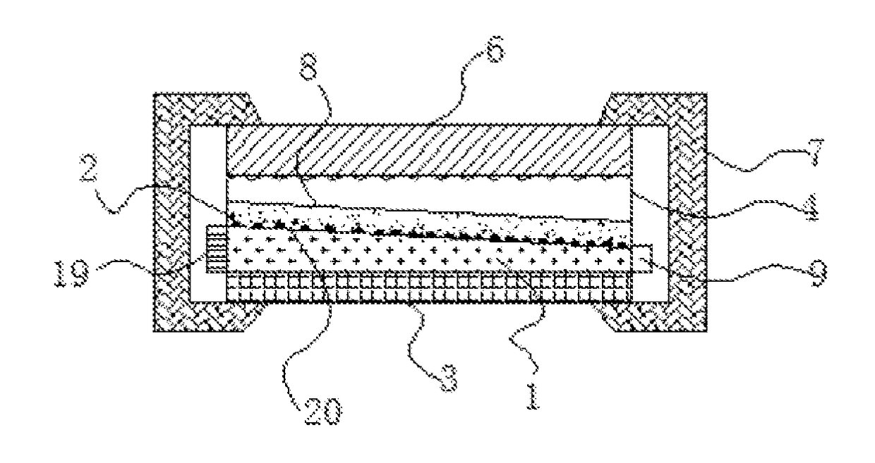
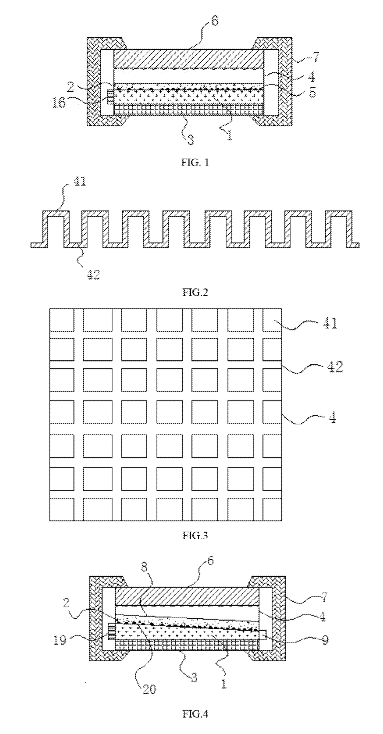
[0156]A flat lamp as shown in FIG. 4, the light guide layer 1 is wedge-shaped with a right-angled trapezoidal cross-section; the thick side of the light guide layer 1 is the light incident side provided with LED light bars 19, and the thin side of the light guide layer is provided with buffer materials 9,wherein the cross section of the buffer layer 4 or the backplane 6 is also a right-angle trapezoid, and the stacked structure composed of the backplane 6, the light guide layer 1, the reflective layer 2 he buffer layer 4 and the diffusion layer 3 is in the shape of a flat plate.

embodiment 2

[0157]A flat lamp, the stacked structure composed of the backplane 6, the light guide layer 1, the reflection layer 2, the buffer layer 4 and the diffusion layer 3 is in the shape of a flat plate structure which is one of the following three:

[0158](1) The light guide layer 1, the buffer layer 4, the reflective layer 2 and the backplane 6 are all in the shape of a flat plate, as shown in FIG. 1;

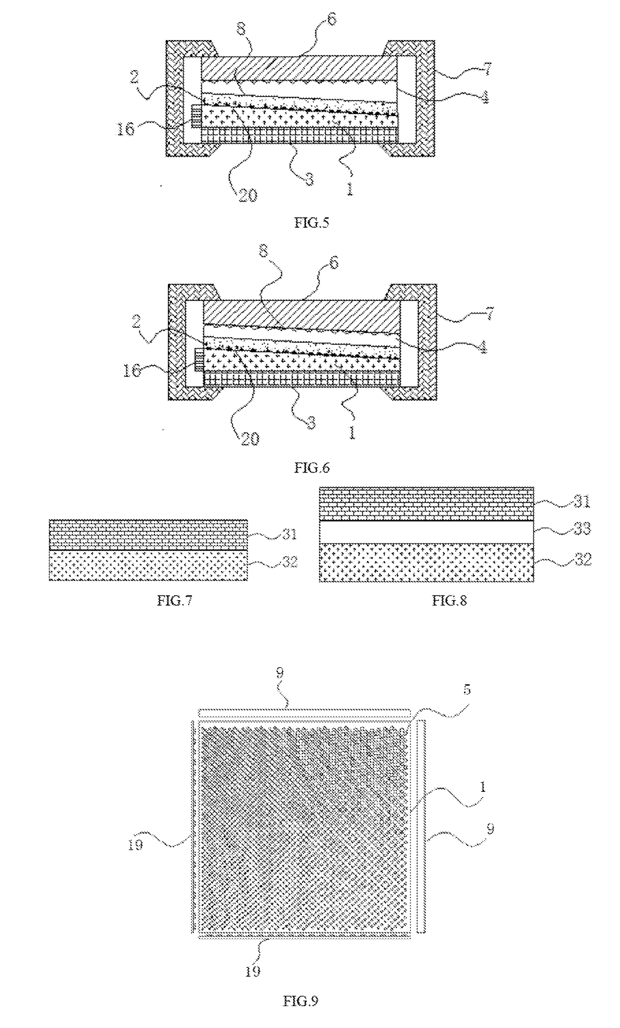
[0159](2) The light guide layer 1 is a wedge-shaped light guide layer with a right-angled trapezoidal cross-section, the buffer layer 4 is a wedge-shaped buffer layer with a right-angled trapezoidal cross-section, and the back face of the light guide layer 1 is a first inclined plane 20, the side of the buffer layer 4 close to the reflection layer 2 is a second inclined plane 8, the first inclined plane 20 is parallel to the second inclined plane 8, the reflection layer 2 is positioned between the first inclined plane 20 and the second inclined plane 8, and the backplane 6 and the reflection l...

embodiment 3

[0162]As shown in FIGS. 7 and 8,the embodiment 3 has a similar structure to that of embodiment 1, except that: the diffusion layer 3 includes a first diffusion monolayer 31 and a second diffusion monolayer 32; the first diffusion monolayer 31 has opposite two faces including a light incident face and a first superimposed face of the diffusion layer 3; the second diffusion monolayer 32 has opposite two faces including a light-emitting face and a second superimposed face of the diffusion layer 3; the first superimposed face of the first diffusion monolayer 31 and the second superimposed face of the second diffusion monolayer 32 are superimposed on each other; the incident face of the first diffusion monolayer 31 and the light-emitting face of the light guide layer 1 are in contact with each other, and the hardness of the first diffusion monolayer 31 is smaller than that of the second diffusion monolayer 32.

[0163]The structure of the diffusion layer is one of the following three:

[0164]...


PUM


Abstract

The present invention disclosed a flat lamp, comprising a light guide layer, a reflective laver, a diffusion layer, a buffer layer, and a backplane, the light guide layer has two opposite faces including a back face and a light emitting face, the reflective layer is located on the back face of the light guide layer, the diffusion layer is located on the light emitting face of the light guide layer, the buffer layer is located between the backplane and the reflective layer, and several light guide points are provided between the reflective layer and the light guide layer, the flat lamp further comprises a light source and an outer frame, with incident points being located on a lateral side of the light guide layer, the stacked structure is in the shape of a flat plate.

Description

CROSS REFERENCE TO RELATED APPLICATIONS[0001]This application is a continuation application in part of International Application No. PCT / CN2017 / 089184, filed on Jun. 20, 2017, which is based upon and claims priority to Chinese Application No. 201610814316.3 filed on Aug. 30 2016, the entire contents of which are incorporated herein by reference.TECHNICAL FIELD[0002]The present invention relates to the technical field of lamps, and particularly relates to a flat lamp.BACKGROUND[0003]The LED (Light Emitting Diode) technology has been widely promoted for the advantages of power saving, high brightness, long service life, and good seismic performance. In recent years, LED lights have become more and more widely used in daily lighting and displays. The more common applications, such as LED lamp panels, that is, a plurality of LED lamp caps are arranged in an array in a lampshade, and the corresponding drive circuit is provided in the lampshade, the structure is simple and practical, but ...

Claims


Application Information

Patent Timeline
IPC IPC(8): F21V8/00
CPCG02B6/0093G02B6/0051G02B6/0058G02B6/009G02B6/0055G02B6/0088G02B6/0076G02B6/0065F21S8/00F21V7/22F21V15/04F21V19/001F21V2200/20F21V19/00G02B6/0046G02B6/0073G02B6/0078G02B6/0085
Inventor SHENG, YULIN
Owner KUNSHAN CHENGTAI ELECTRIC
Why Eureka
Try Eureka