Ink composition for light sintering, wiring board using same and manufacturing method therefor

Active Publication Date: 2017-04-27
KOREA ELECTRONICS TECH INST
View PDF4 Cites 16 Cited by
  • Summary
  • Abstract
  • Description
  • Claims
  • Application Information

AI Technical Summary

Benefits of technology

[0045]In accordance with the present invention, when a wiring pattern of a wiring board is formed using cheap copper nanoparticles having copper oxide films (hereinafter referred to as “copper oxide nanoparticles”) as a raw material of a conductive ink, production cost of the wiring board may be reduced. That is, since a wiring pattern of a wiring board can be formed using a conductive ink including copper oxide nanoparticles, which are cheaper than pure copper nanoparticles, production cost of a wiring board may be reduced.
[0046]In addition, upon sintering after printing the conductive ink including the copper oxide nanoparticles on a wiring board, copper oxide films formed on surfaces of the copper nanoparticles may be removed by performing short-wavelength light irradiation instead of thermal sintering. Accordingly, process time may be shortened and damage of the wiring board may be prevented by a sintering process through the short-wavelength light irradiation. Here, the copper oxide nanoparticles are in an insulation state before the light sintering, but are reduced into pure copper nanoparticles by the light sintering, thereby forming a wiring pattern made of copper having electrical conductivity.
[0047]Accordingly, by applying the conductive ink according to the present invention to a board body of a flexible printed circuit board used in a digitizer, a wiring pattern may be formed without damaging the board bod

Problems solved by technology

However, silver included in conductive inks is very expensive and thus, when wiring patterns are formed using the conductive inks, there is limitation in reducing fabrication costs of resultant wiring boards.
In addition, since a thermal sintering process is required, there

Method used


Image

  • Ink composition for light sintering, wiring board using same and manufacturing method therefor
  • Ink composition for light sintering, wiring board using same and manufacturing method therefor
  • Ink composition for light sintering, wiring board using same and manufacturing method therefor

Examples


Example

First Example

[0074]An ink composition for light sintering according to a first example includes copper oxide nanoparticles having copper oxide films, a reducing agent for reducing copper oxidized by light irradiation to form copper nanoparticles, a dispersing agent, a binder, and a solvent.

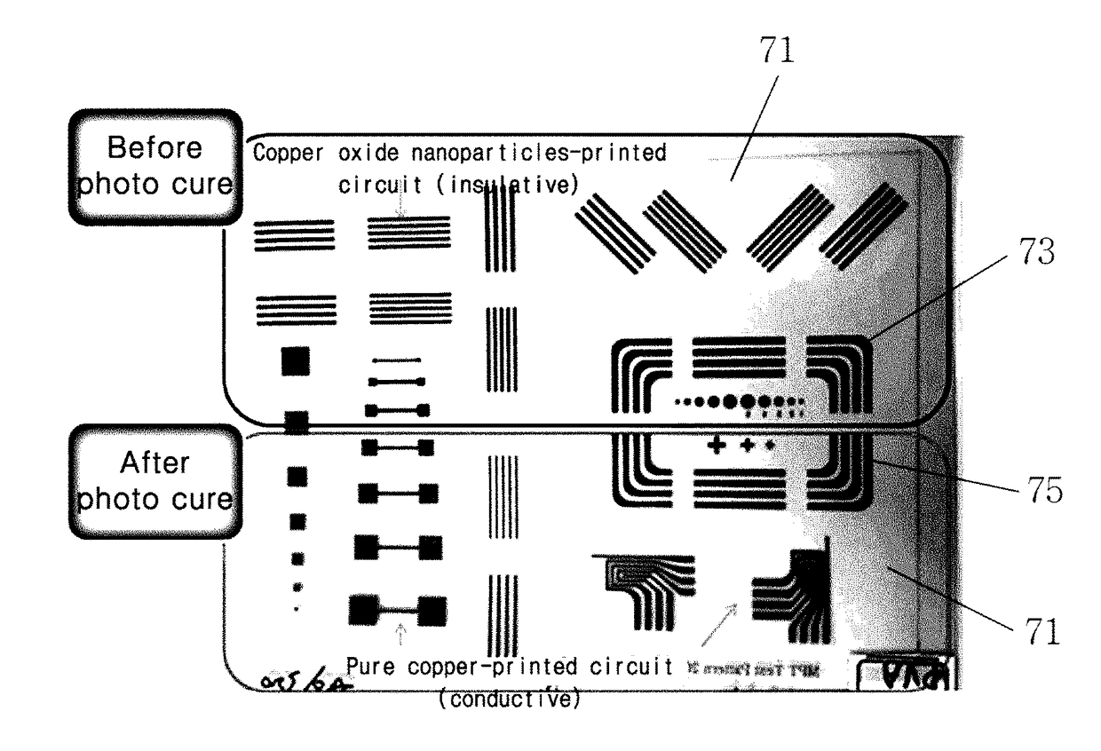
[0075]Although copper oxide nanoparticles are nonconductors, the copper oxide nanoparticles are converted into pure copper nanoparticles having electrical conductivity by light irradiation, thus being used as a source of a conductor. The copper oxide nanoparticles are core-shell type particles, may have a structure wherein a copper oxide film is formed so as to have a thickness of 500 nm or less on surfaces of copper nanoparticles, and may have a particles size of less than 1 μm. With regard to this, when the copper oxide film is coated so as to have a thickness of greater than 500 nm, a portion of the copper oxide film might not be reduced into copper by light irradiation. Accordingly, the copper...

Example

[0130]Here, an ink composition for light sintering according to Example 1 used to fabricate the wiring board according to the first example was prepared as follows. 120 g of copper oxide nanoparticles having a copper oxide film of a thickness of about 5 nm and a particle size of 100 nm, 0.3 g of a dispersing agent, 15 g of polyvinylpyrrolidone, and 1 g of ascorbic acid were added to 60 g of ethylene glycol and then mixed. A resultant mixture was pre-dispersed for one hour in a pre-disperser and highly-dispersed in a 3-roll mill, thereby preparing an ink composition for light sintering.

[0131]The ink composition for light sintering according to Example 1 was screen-printed on the board body 71 made of polyimide and then dried at 90° C. for 30 minutes, thereby forming the preliminary wiring pattern 73.

[0132]Subsequently, white light generated from a xenon flash lamp was irradiated to the preliminary wiring pattern 73, thereby forming the wiring pattern 75. Here, specific resistance cha...

Example

Second Example

[0139]An ink composition for light sintering according to a second example includes silver oxide and copper oxide nanoparticles having copper oxide films and may further include a reducing agent for reducing copper oxidized by light irradiation to form copper nanoparticles, a dispersing agent, a binder, and a solvent.

[0140]The silver oxide is silver oxide (I) or silver oxide (II). Here, the silver oxide (I) is Ag2O which is dark brown to blackish brown, has a specific gravity of 7.22, and is degradable at about 160° C. The silver oxide (II) is AgO which is charcoal gray, has a specific gravity of 7.483, and is degradable at about 100° C.

[0141]When xenon white light is irradiated to such silver oxide, optical absorption may be easily performed due to the color, i.e., brown or black, of the silver oxide. In addition, decomposition may be easily performed and thus sintering may be easily performed. Further, a denser wiring pattern may be fabricated. Hereinafter, a light s...


PUM

PropertyMeasurementUnit
Temperatureaaaaaaaaaa
Timeaaaaaaaaaa
Timeaaaaaaaaaa

Abstract

The present invention relates to an ink composition for light sintering, a wiring board using the same, and a method of fabricating the wiring board. The present invention aims to provide formation of a wiring pattern without damage to thin and soft wiring boards such as a flexible printed circuit board. The present invention provides an ink composition for light sintering including copper oxide nanoparticles having copper oxide films, a reducing agent for reducing copper oxidized by light irradiation to form copper nanoparticles, a dispersing agent, a binder, and a solvent

Description

TECHNICAL FIELD[0001]The present invention relates to an ink composition, a wiring board using the same, and a method of fabricating the wiring board using the ink composition, and more particularly, to an ink composition for light sintering including copper nanoparticles having copper oxide films, a wiring board using the same, and a method of fabricating the wiring board.BACKGROUND ART[0002]Conductive inks currently used in printed electronics are mainly used to form wiring patterns on wiring boards such as display panels, solar cell panels, digitizers, and printed circuit boards.[0003]As such conductive inks, silver (Ag)-containing inks and silver pastes are mainly used. The silver-containing conductive inks may include, other than silver, metallic particles such as gold, platinum, and palladium.[0004]The silver inks or silver pastes are formed into wiring patterns on wiring boards through a thermal sintering process. However, silver included in conductive inks is very expensive ...

Claims


Application Information

Patent Timeline
IPC IPC(8): H05K1/09C09D11/037H01B1/22B22F1/00H05K3/22H05K3/02B22F1/02C09D11/52H05K3/12B22F1/0545B22F1/107B22F1/16
CPCH05K1/095C09D11/52C09D11/037H01B1/22H05K3/1216H05K3/227B22F2302/25H05K1/097B22F1/02B22F1/0074B22F1/0022H05K2201/032B22F2301/10H05K3/027B22F9/24H01B1/20B22F1/107B22F1/16B22F1/0545
Inventor KIM, YOONJINCHO, JINWOOSHIN, KWONWOOSEO, YONGGONKIM, YEONWONJANG, SANGHYEONJO, NAMJE
Owner KOREA ELECTRONICS TECH INST
Why Eureka
Try Eureka