Method for determining correction values for correcting positional measurement errors in a machine having at least one translational axis of movement

Inactive Publication Date: 2008-06-26
CARL ZEISS IND MESSTECHN GMBH
View PDF7 Cites 17 Cited by
  • Summary
  • Abstract
  • Description
  • Claims
  • Application Information

AI Technical Summary

Benefits of technology

[0014]Against this background, it is an object of the present invention to provide for a method which enables a reduction in the production costs of a coordinat

Problems solved by technology

However, it is known that the accuracy in the determination of the spatial position of the head is limited.
In other words, each measurement is affected by measurement errors.
The measurement errors have various causes.
These include the limited accuracy with which material measures can be produced.
However, even in the case of relatively small coordinate measuring machines small manufacturing tolerances in the material measures are already enough to affect the measuring accuracy of the machine.
Sometimes, defects in the material measures come to light only after they have been installed in the coordinate measuring machine, and this is particularly disadvantageous since the “poor” material measures must subsequently be exchanged.
The production costs of a coordinate measuring machine therefore depend strongly on the quality and the costs of the material measures.
The greater the spacings at which correction values are determined, the more

Method used


Image

  • Method for determining correction values for correcting positional measurement errors in a machine having at least one translational axis of movement
  • Method for determining correction values for correcting positional measurement errors in a machine having at least one translational axis of movement
  • Method for determining correction values for correcting positional measurement errors in a machine having at least one translational axis of movement

Examples


Example

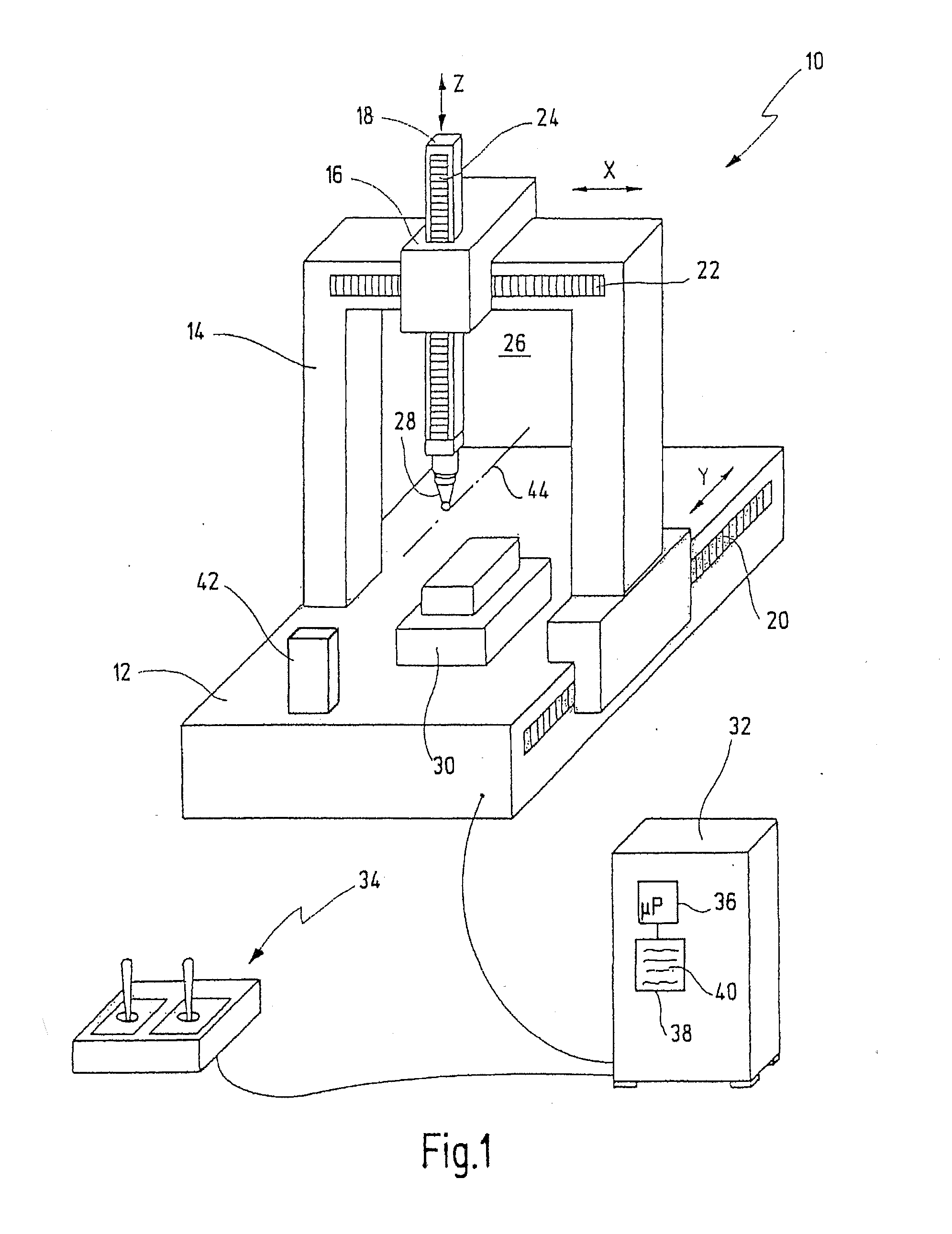
[0051]In FIG. 1, reference numeral 10 designates an exemplary embodiment of a coordinate measuring machine in its entirety. The coordinate measuring machine 10 is illustrated in a portal structure here. However, the invention is not restricted to this, and can likewise be used in the case of coordinate measuring machines of different structure, for example coordinate measuring machines having a horizontal cantilever arm. Moreover, as already mentioned at the beginning, the invention can also be used with all other machines in which a head is moved along at least one translational path of movement, and in which the positions of the head must be determined.

[0052]The coordinate measuring machine 10 has a base 12 upon which a portal 14 is moveably arranged. The direction of movement of the portal 14 is designated as the Y-axis. A carriage 16 which can be moved in the X-direction is arranged on the crossbeam of the portal 14. Seated on the carriage 16 is a quill 18 which can be moved in ...


PUM


Abstract

In a coordinate measuring machine or any other kind of machine having at least one translational movement axis, correction values are determined by moving the mobile head of the machine along a defined path of movement. First and second position data are recorded by means of first and second position measuring devices. The first position data originate from position measuring devices of the machine. The second position data result from a reference measurement. The correction values are determined as a function of the first and second position data. A defined number of correction values is determined for each section of the path of movement, with the defined number varying in the sections as a function of the error profile defined by the correction values.

Description

CROSS REFERENCES TO RELATED APPLICATIONS[0001]This application is a continuation of international patent application PCT / EP2006 / 004641, filed on May 17, 2006 designating the U.S., which international patent application has been published in German language as WO 2006 / 133782 A1 and claims priority from German patent application 10 2005 028 788.3, filed on Jun. 16, 2005. The entire contents of these priority applications are incorporated herein by reference.BACKGROUND OF THE INVENTION[0002]The present invention relates to a method for determining correction values for correcting positional measurement errors in a machine having at least one translational movement axis, such as, in particular in a coordinate measuring machine. The invention further relates to a coordinate measuring machine having a memory for storing correction values which have been determined in accordance with such a method.[0003]Coordinate measuring machines are typically used to measure the shape of a measurement ...

Claims


Application Information

Patent Timeline
IPC IPC(8): G01C25/00
CPCG01D5/24452G01D18/008G01D5/2449G01D18/001
Inventor STAADEN, ULRICHGRUPP, GUENTERAUBELE, EUGEN
Owner CARL ZEISS IND MESSTECHN GMBH
Why Eureka
Try Eureka