Power-feeding device

a power supply coil and power supply technology, applied in the direction of rail devices, charging stations, transportation and packaging, etc., can solve the problems of vibration, change of the position of the power supply coil, and vibration in the power supply apparatus, so as to reduce the amount of excess output or increase the effect of magnetic flux leakag

Active Publication Date: 2018-08-09
PANASONIC AUTOMOTIVE SYST CO LTD
View PDF13 Cites 0 Cited by
  • Summary
  • Abstract
  • Description
  • Claims
  • Application Information

AI Technical Summary

Benefits of technology

The present invention allows for the reduction of excessive output or magnetic flux leakage by controlling the amount of power supply in case of an emergency situation.

Problems solved by technology

In this case, when an earthquake occurs or when a large vehicle passes by, vibration occurs in the power supply apparatus and the position of the power supply coil changes.
When a wireless power supply system to supply power to a portable device is mounted on a mobile unit such as a vehicle, vibration occurs and the position of the power supply coil changes as the mobile unit moves.
When the position of the power supply coil changes during power supply, coupling between the power supply coil and the power receiving coil changes, causing excessive output or an increase in magnetic flux leakage.

Method used


Image

  • Power-feeding device
  • Power-feeding device
  • Power-feeding device

Examples


embodiment

[0015]

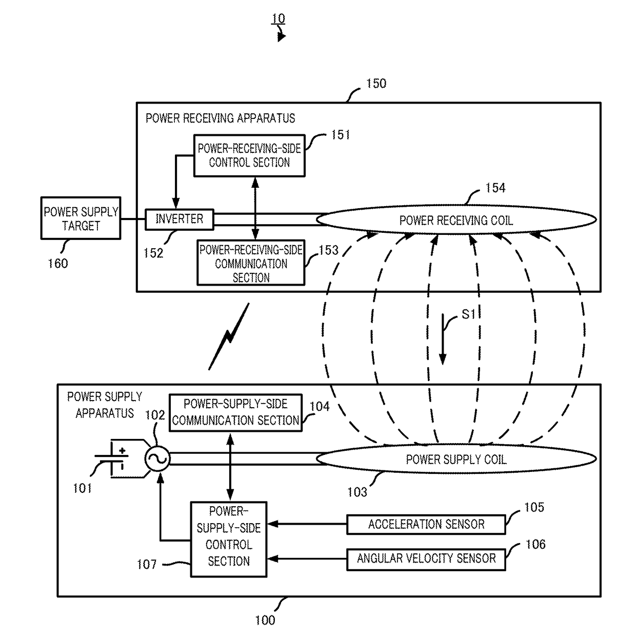
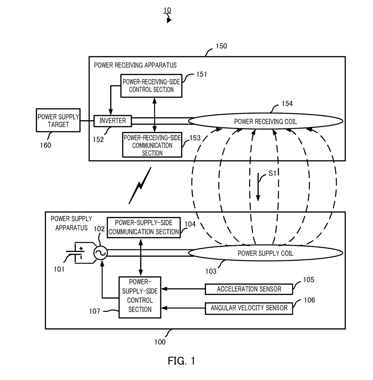
[0016]A configuration of power supply system 10 according to an embodiment of the present invention will be described using FIG. 1.

[0017]Power supply system 10 is mainly composed of power supply apparatus 100, power receiving apparatus 150 and power supply target 160.

[0018]Power supply apparatus 100 supplies power to power receiving apparatus 150.

[0019]By receiving power supply from power supply apparatus 100, power receiving apparatus 150 supplies power to power supply target 160.

[0020]Power supply target 160 is a load or battery, for example.

[0021]Power supply system 10 is used when charging in a wireless manner a battery which is mounted on a vehicle, when charging in a wireless manner a battery incorporated in an electric device such as a mobile phone or when supplying power to a load such as a motor to drive the load. When a vehicle-mounted battery is charged in a wireless manner, power supply apparatus 100 is installed on the ground such as a parking area and power recei...


PUM


Abstract

To minimize excessively high output or increases in magnetic-flux leakage by controlling power feeding on the power-feeding side if an unforeseen situation occurs. This power-feeding device (100) feeds power to an external power-receiving device (150) in a contactless manner. A power-feeding coil (103) uses electromagnetic power to feed electrical power to a power-receiving coil (154) in the power-receiving device (150). While power is being fed from said power-feeding coil (103), a power-feeding-side control unit (107) determines the amount of displacement of the power-feeding coil (103) and, on the basis of the determined displacement amount, controls the amount of electrical power being fed.

Description

RELATED APPLICATION[0001]This application is a continuation of U.S. patent application Ser. No. 14 / 778,425 filed Sep. 18, 2015, which is incorporated herein by reference in its entirety.TECHNICAL FIELD[0002]The present invention relates to a power supply apparatus that supplies power to an external power receiving section using an electromagnetic force in a wireless manner.BACKGROUND ART[0003]Conventionally, wireless power supply systems have been known in which power is supplied while a power supply coil and a power receiving coil are placed facing each other in a wireless manner. In such wireless power supply systems, when vibration is added to the power supply side during power supply due to an earthquake or the like, the position of the power supply coil changes.[0004]For example, in a wireless power supply system that supplies power to a power storage apparatus mounted on a vehicle such as an electric vehicle, a power supply apparatus is installed on the ground. In this case, w...

Claims


Application Information

Patent Timeline
Patent Type & Authority Applications(United States)
IPC IPC(8): H02J50/12H02J50/90H02J50/80H02J50/10H02J7/02B60L11/18B60M7/00
CPCH02J50/90H02J50/80H02J50/10Y02T90/122Y02T90/14Y02T10/7072H02J7/025Y02T90/12Y02T90/125B60L11/1829Y02T10/7005B60L11/182H02J50/12Y02T90/121B60L53/38B60L53/122H02J7/00034Y02T10/70
Inventor NISHIO, TSUYOSHIOHASHI, OSAMUASAOKA, NORIAKIKOIZUMI, MASAYOSHI
Owner PANASONIC AUTOMOTIVE SYST CO LTD
Why Eureka
Try Eureka