Real-time video extensometer

a real-time video and extensometer technology, applied in the field of real-time video extensometer, can solve the problems of system consumption of an entire image, high cost, and restrictive aspect of measuring strain with a video device, and achieve the effects of improving accuracy, high frequency images, and low latency times

Active Publication Date: 2019-12-10
ILLINOIS TOOL WORKS INC
View PDF15 Cites 0 Cited by
  • Summary
  • Abstract
  • Description
  • Claims
  • Application Information

AI Technical Summary

Benefits of technology

[0010]Embodiments of this disclosure address the above-identified deficiencies by combining the image source, data processing and electrical output on to a single processing board in order to achieve high frequency images and low latency times on data flow. Further, the data processing engine or FGPA (field programmable gate array) processes the image on a pixel basis and updating the output the intermediate strain result so that after receipt of the final image pixel, a final extension / strain value is achieved and immediately output for evaluation. This hardware and process makes the real-time video extensometer similar to traditional electro-mechanical devices (such as clip-ons) and allows them to be connected and used by materials testing systems in the same manner. The net result of the high speed real-time video processing is the greatly improved accuracy, much faster tracking of the specimen elongation and very low latency data which allows the user to perform and meet a complete range of testing standards.
[0011]The real-time video extensometer combines the image inputs, data processing engine and extension / strain data output onto a single video processing board to minimize input and output data latency and maximize processing speed. The video processing board also eliminates the external latency and processing time issues related to operating systems. The primary reason for the improvement with respect to the processing system is the implementation of the entire algorithm on the FPGA (field programmable gate array) portion of the data processing system. The design and implementation makes the entire data path from input occur in hardware and therefore the entire system is deterministic and high speed.

Problems solved by technology

However, a significant restrictive aspect of measuring strain with a video device is collecting the images at significant speed, providing the images to an image processing engine, processing the images to produce a displacement or strain value, outputting the strain value in a software consumable format and synchronizing it with other data collected via traditional real-time methods (e.g. load cells have electrically balanced bridges).
The main drawback to most of the systems is they use an off-the-shelf high speed machine vision camera, transmit the images via a high speed bus to a processing system, manipulate the images using a standard or dedicated processing system such as a PC or microcontroller and then output the data internally to software on the processing system or via convertors to electrical signals.
Typically these systems consume an entire image and work on the array of pixels to produce a strain or displacement value.
Computing strain or displacement in this manner is computationally intensive and requires a large microprocessor system.
After computation of the strain or displacement data, it is output to the software on a PC which requires a specialized interface and is not very portable or output via an analog or encoder device.
These systems have issues with respect to time latency, integration and required computational power.

Method used


Image

  • Real-time video extensometer
  • Real-time video extensometer
  • Real-time video extensometer

Examples


Embodiment Construction

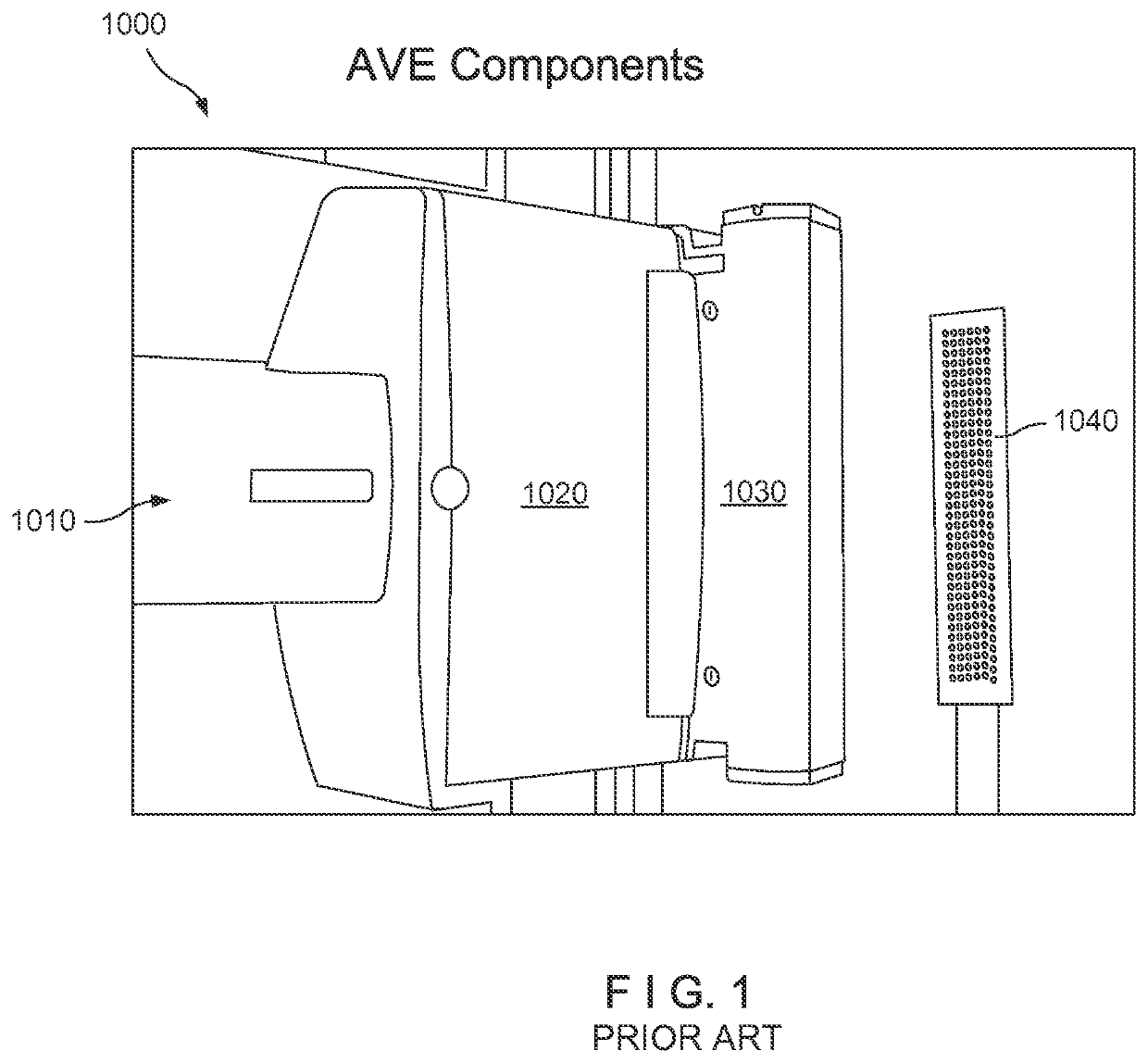
[0017]Referring now to the drawings in detail wherein like numerals refer to like elements throughout the several views, one sees that FIG. 1 is an extensometer 1000 of the prior art. This extensometer 1000 utilizes an external camera, PC and data communications to capture images and produce extension / strain values. The extension / strain data is calculated by software in both the PC and via analog outputs. More specifically, electronics housing 1010 holds a printed circuit board, a camera (typically with a polarizing and light filter), and lenses for different fields of view. The image received by the camera is taken through a constant density air tube (CDAT) 1020. An integral illumination unit 1030 is fixed to the side of the constant density air tube (CDAT) 1020. Further, a two-dimensional calibration fixture 1040 is provided.

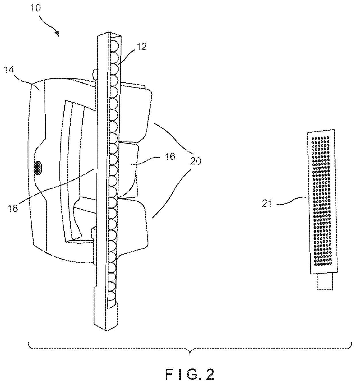
[0018]FIG. 2 illustrates the external appearance of an embodiment of the real-time video extensometer 10 of the present disclosure. The real-time video extens...


PUM

PropertyMeasurementUnit
stressaaaaaaaaaa
constant densityaaaaaaaaaa
displacementaaaaaaaaaa

Abstract

This disclosure relates to a real-time video extensometer. Typically, the apparatus of the disclosure combines the image source, data processing and electrical output on to a single processing board in order to achieve high frequency images and low latency times on data flow. Further, the video processing engine processes the image on a pixel basis and updating the output the intermediate extension / strain result so that after receipt of the final image pixel, a final extension / strain value is achieved and immediately output for evaluation.

Description

RELATED APPLICATIONS[0001]This application is a national phase of International Application No. PCT / US2015 / 037723 filed Jun. 25, 2015 and claims priority Provisional Application No. 62 / 029,650, filed on Jul. 28, 2014, the contents of which is hereby incorporated by reference in its entirety and for all purposes.BACKGROUND OF THE DISCLOSURE[0002]Field of the Disclosure[0003]The disclosure relates to a method of real-time measuring strain and related data by use of video methods.[0004]Description of the Prior Art[0005]Video extensometry is known in the prior art and well-developed for its intended purposes. However, a significant restrictive aspect of measuring strain with a video device is collecting the images at significant speed, providing the images to an image processing engine, processing the images to produce a displacement or strain value, outputting the strain value in a software consumable format and synchronizing it with other data collected via traditional real-time metho...

Claims


Application Information

Patent Timeline
Patent Type & Authority Patents(United States)
IPC IPC(8): G01B11/16G01N3/06G01N3/08H04N7/10G06T7/246H04N7/18
CPCH04N7/188H04N7/10G01N3/068G01N3/08G06T7/246G06T2207/30208G01N2203/0647G01B11/16G01N2203/0016G01N3/06
Inventor PETERSON, MARTIN A.DINA, DANIEL
Owner ILLINOIS TOOL WORKS INC
Why Eureka
Try Eureka