
Methods and Designs for Balancing a Stranded Termination Assembly

a technology of stranded termination and assembly, applied in the field of methods, can solve the problems of difficult organization, more complicated end fittings, and difficult handling of synthetic filaments

Active Publication Date: 2018-08-30
BRIGHT TECH CO LTD
View PDF25 Cites 11 Cited by
  • Summary
  • Abstract
  • Description
  • Claims
  • Application Information

AI Technical Summary

Benefits of technology

The invention is about devices and methods for connecting cables to a collector in a way that distributes the load evenly among the cables' strands. Each strand termination is connected to the collector using a strand tensioner, which adjusts the tension in the cable to achieve a desired load distribution. The method allows for the easy creation of a repeatable and efficient connection between the strands and the collector.

Problems solved by technology

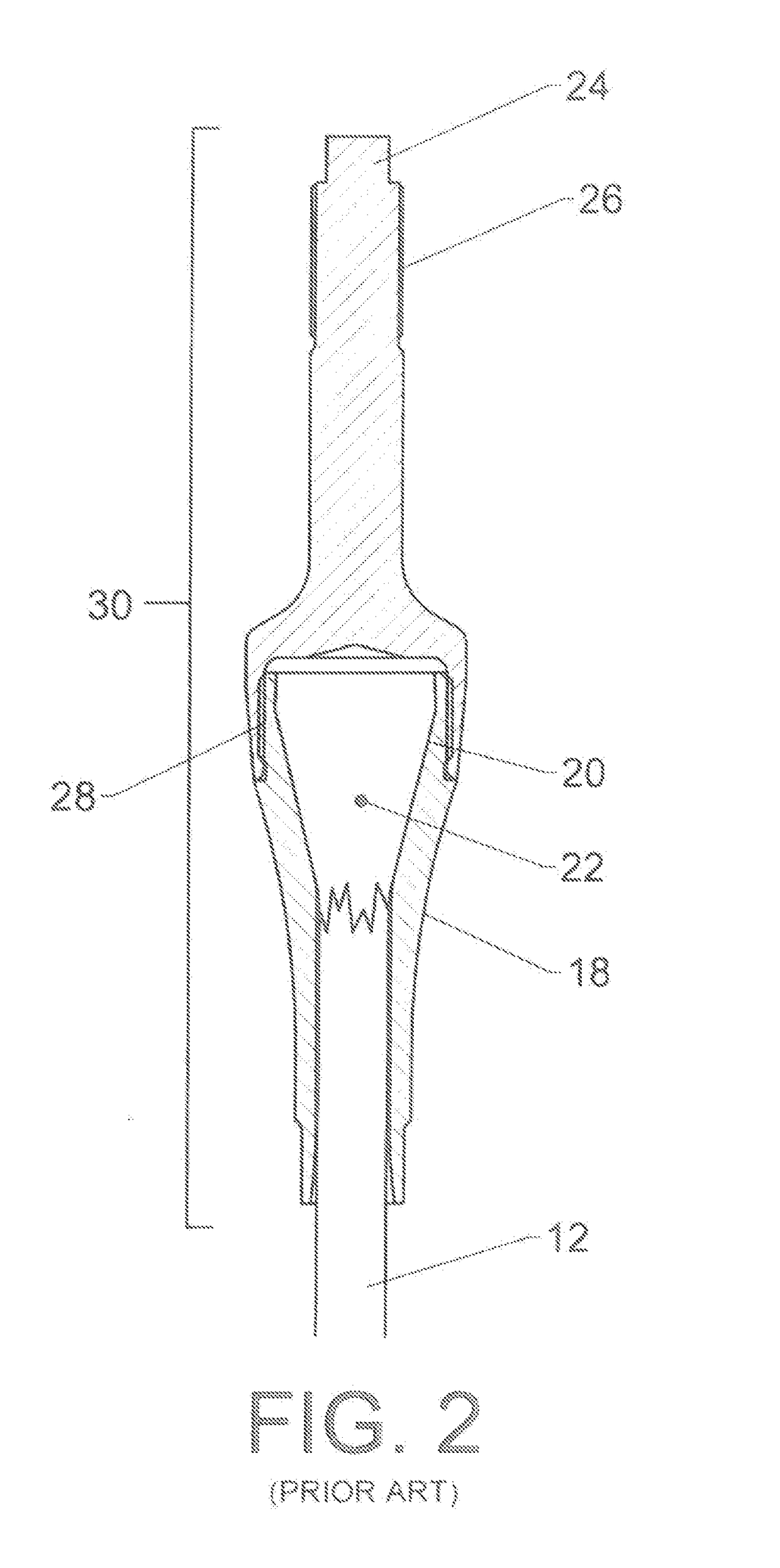
For larger cables, however, more complicated end-fittings are needed in order to produce acceptable break strength.
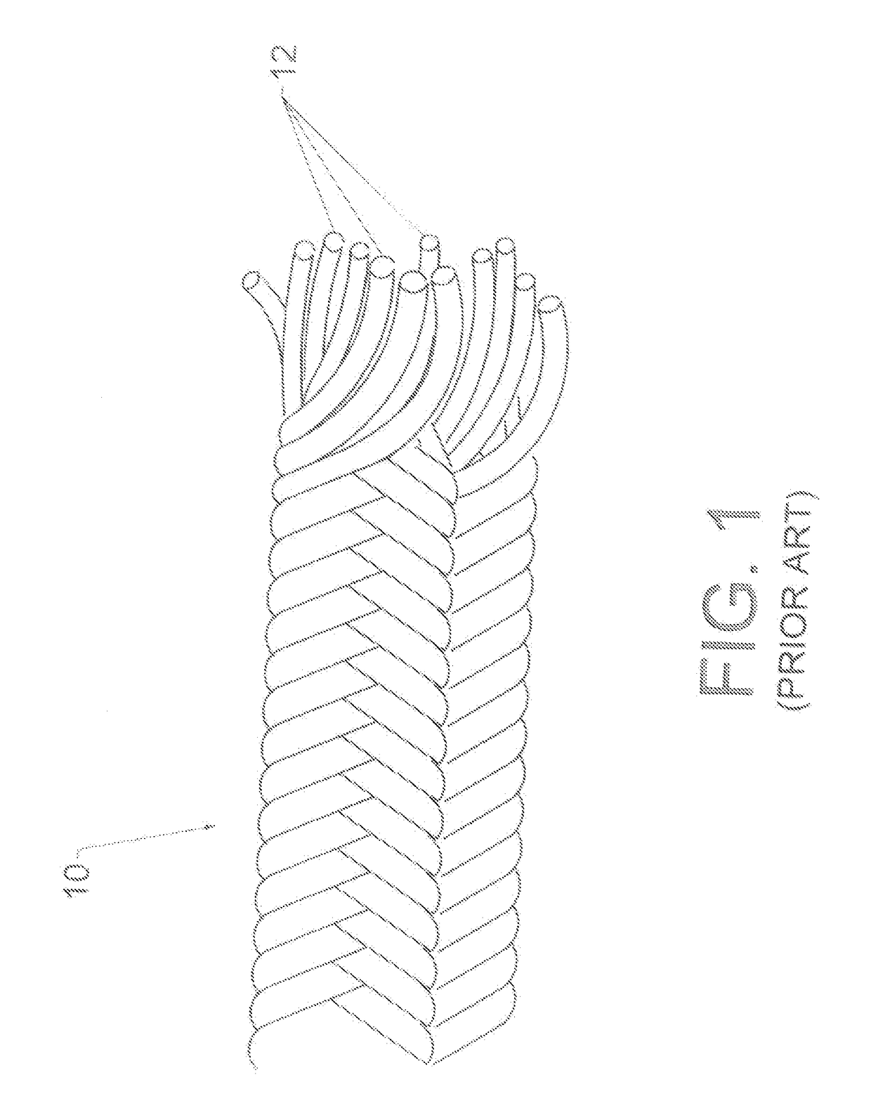
The filaments are very strong in tension, but they are not very rigid.
These facts make such synthetic filaments difficult to handle during the process of adding a termination and difficult to organize.
While the invention could in theory be applied to older cable technologies—such as wire rope—it likely would offer little advantage and the additional time and expense of implementing the invention would not be worthwhile.
When a cable has non-parallel strands the interrelationship between the strands becomes quite complex.
This is obviously an undesirable result.
The cutting and terminating processes are inherently imperfect.
However, when a cable made of synthetic filaments is first terminated and loaded, the manufacturing tolerances will generally cause some strands to shift or “slip” relative to others—thereby altering the proportional load sharing that was intended.

Method used


Image

  • Methods and Designs for Balancing a Stranded Termination Assembly
  • Methods and Designs for Balancing a Stranded Termination Assembly
  • Methods and Designs for Balancing a Stranded Termination Assembly

Examples


Embodiment Construction

[0120]FIG. 4 shows an exemplary device used to gather all the strands into a unified whole and thereby create an overall cable termination. Collector 34 includes twelve receivers 38, each of which is configured to connect to a single strand termination (In other embodiments a receiver may be configured to connect to multiple strand terminations). Collector 34 typically includes some type of load-transferring feature designed to transfer a load from the collector to some external element. Loading flange 36 is a simple example of a load-transferring feature. The collector in this example is very simplistic and is unlikely to represent a design that would actually be used. However, it does serve well to clearly illustrate the inventive features.

[0121]FIG. 5 shows an exemplary connection between a termination on a strand and the collector. Loading stud 24 is passed through opening 46 and through receiver 38 in collector 34. Receiver 38 includes a hemispherical concave portion sized to a...


PUM


Abstract

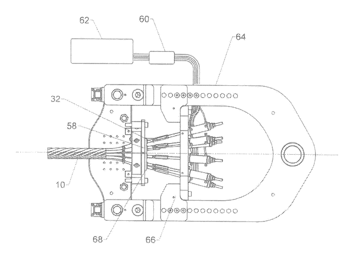
Devices and methods for loading a cable in order to create a desired distribution of the load among the cable's constituent strands. Strand terminations are applied to many—and possibly all of—the cable's strands. The ultimate goal is to connect the strand terminations to a collector in order to create an overall cable termination. The relationship between each strand termination and the collector is allowed to “float” using the inventive process while the cable is tensioned and an appropriate spatial relationship between each strand tensioner and the collector is determined. Once the appropriate relationship is found, it is configured to be repeatable (such as by recording its position for later application to the same or similar collector).

Description

CROSS-REFERENCES TO RELATED APPLICATIONS[0001]This non-provisional patent application claims the benefit of an earlier-filed non-provisional application. The patent application was assigned Ser. No. 14 / 697,551. It listed the same inventor.STATEMENT REGARDING FEDERALLY SPONSORED RESEARCH OR DEVELOPMENT[0002]Not Applicable.MICROFICHE APPENDIX[0003]Not ApplicableBACKGROUND OF THE INVENTIONField of the Invention[0004]This invention relates to the field of tensile strength members such as multi-stranded synthetic cables. More specifically, the invention comprises devices and methods for balancing the load carried by a synthetic cable among its constituent strands.Description of the Related Art[0005]A cable must generally be provided with one or more end connections in order to be useful. The end connections allow the cable to carry and transmit a useful load. An end connection may be a simple device—such as a large hook—employed to connect the cable to an anchoring point. Larger syntheti...

Claims


Application Information

Patent Timeline
Patent Type & Authority Applications(United States)
IPC IPC(8): F16G11/12D07B9/00D07B5/00
CPCF16G11/12D07B9/00D07B5/00D07B2201/1096D07B2401/2055F16G11/025
Inventor CAMPBELL, RICHARD V.
Owner BRIGHT TECH CO LTD
Learn More