Stump auger

a technology of auger and stump, which is applied in the field of stump auger, can solve the problems of potential hazards, no design to date has found market acceptance, and the traditional stump grinder is labor-intensive to opera

Active Publication Date: 2018-09-13
LOWE GARETH
View PDF17 Cites 4 Cited by
  • Summary
  • Abstract
  • Description
  • Claims
  • Application Information

AI Technical Summary

Benefits of technology

The present invention is a stump auger for cutting and destroying tree stumps. It includes a main shaft connected at a top end to a drive mechanism for turning the shaft about a vertical axis. The main shaft is connected at a bottom end to a cone top. The cone has a spiral thread extending about its outer surface from the cone top to the bottom. The stump auger also includes at least two boring bars connected to the main shaft, each boring bar including at least two third blades. The third blades have blade edges on a front face for shaving, grinding, and chipping the tree stump as the stump auger rotates about the vertical axis and penetrates the tree stump. The third blades are oriented parallel along a bar axis with a rise angle between 10 and 30 degrees relative to horizontal. The stump auger may also include fourth blades attached to the outer end of the boring bar. The thread has a pitch between 0.5 and 4.0 inches per revolution. The technical effects of the invention include improved cutting and destroying of tree stumps with a stump auger that is efficient and effective in removing the stump.

Problems solved by technology

The traditional style stump grinder tends to be labour intensive to operate and involves potential hazards due to the speed of rotation of the grinding wheel.
Additionally the operator is never certain when he may hit resulting in potential kickback of the machine.
There have been some attempts to develop a stump grinder which rotates not about a horizontal axis but rather about a vertical axis 151 however none of the designs to date have found market acceptance due to their inability to efficiently and effectively remove the stump.
Unfortunately there are a number of drawbacks including slow removal rates, incomplete removal, very high maintenance costs, and lack of efficiency of these devices in effectively removing stumps in a timely and efficient manner.

Method used


Image

  • Stump auger
  • Stump auger
  • Stump auger

Examples


Embodiment Construction

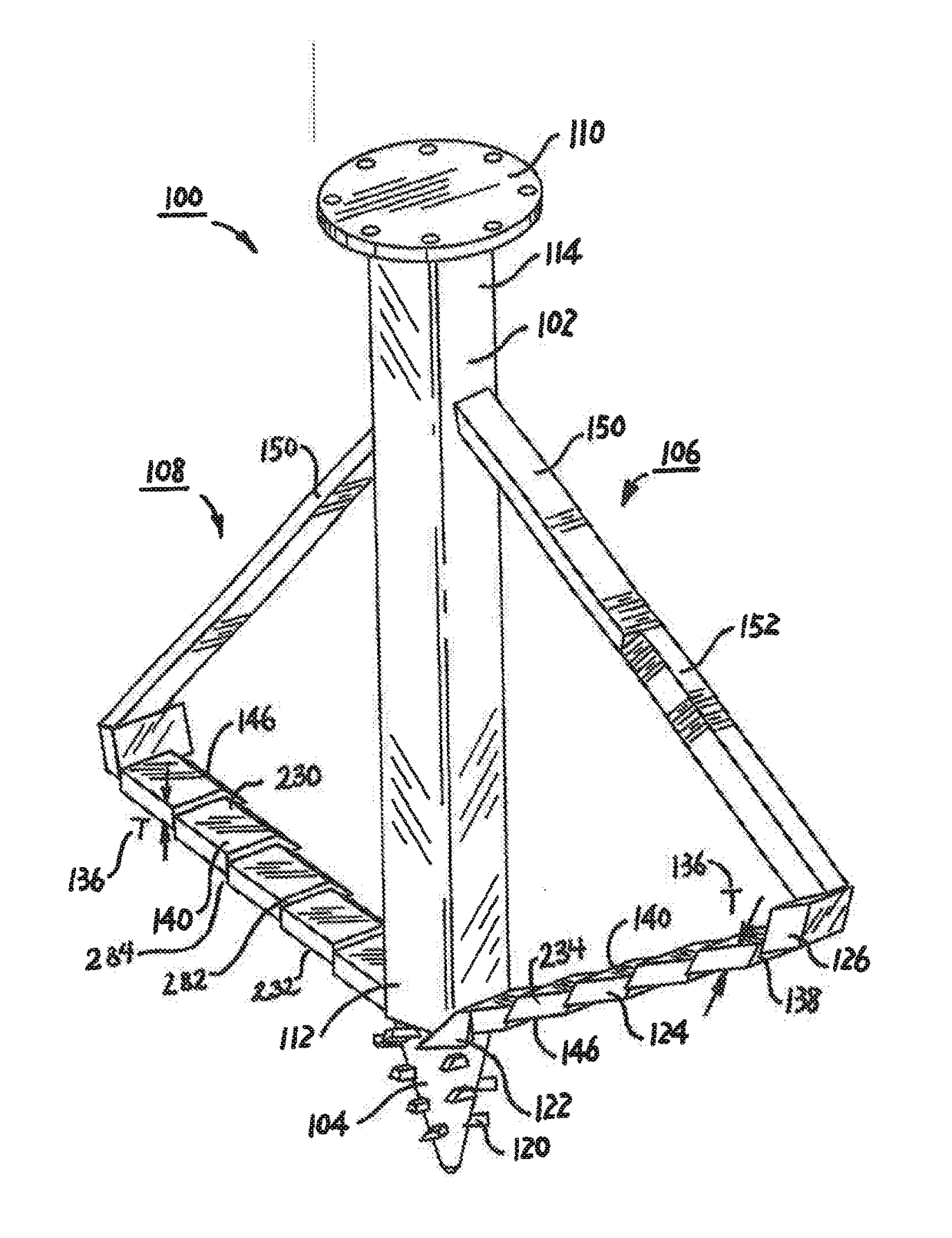
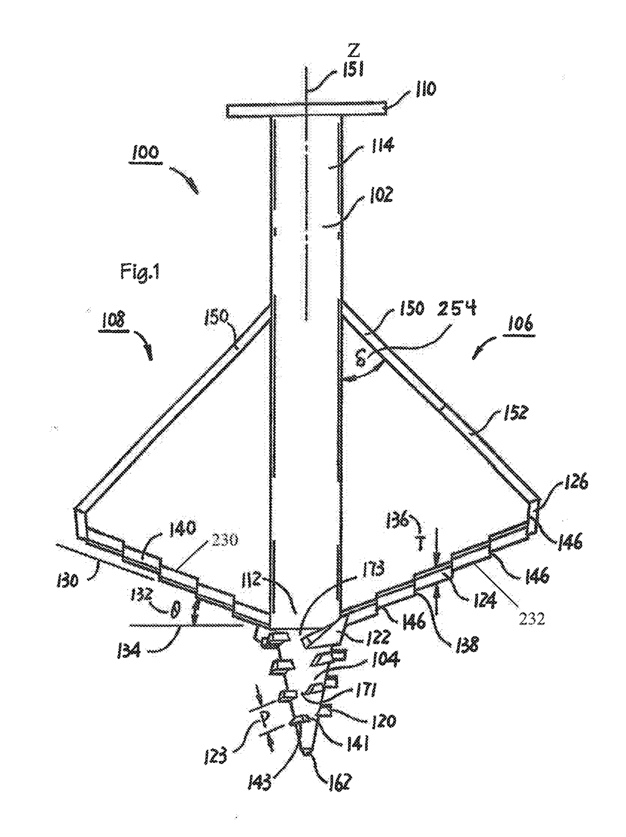
[0055]The present concept a stump auger is shown in FIGS. 1 through 5 generally as stump auger 100.

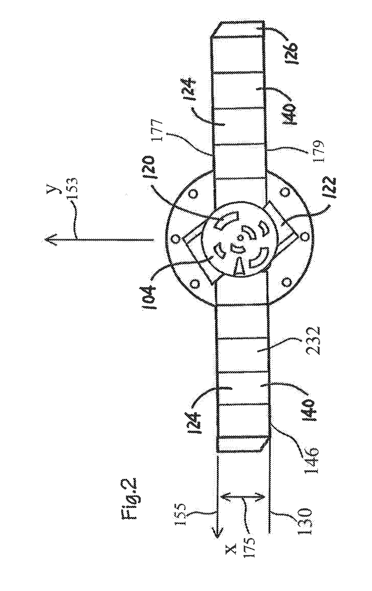
[0056]Stump auger 100 includes the following major components namely a main shaft 102, a cone 104, a first arm 106, a second arm 108, and a flange 110. An arm is defined in this application as a strut 150, a fourth blade 126, a number of third blades 124 all oriented as shown in FIG. 1 and connected together and attached at one end to approximately the bottom end 112 of main shaft 102 and at a location close to the top end 114 of main shaft 102, namely where strut 150 attaches to main shaft 102.

[0057]Each boring bar includes an inner end 292, and an outer end 294, third blades 124 are mounted in stepped offset side by side fashion such that each successive third blade 124 bottom surface 232 is stepped vertically higher an additional offset 138 amount spaced from bar axis 130 wherein the inner face 282 of one third blade abuts the outer face 284 of the adjacent third blade. Preferably t...


PUM


Abstract

The present concept is a stump auger used for cutting and destroying a tree stumps, the stump auger includes a main shaft connected at a top end to a drive mechanism for turning the shaft about a vertical axis, wherein the main shaft is connected at a bottom end to a cone top such that the cone is part of the main shaft. The stump auger cone includes a spiral thread extending about the outer surface of the cone from the cone top to the cone bottom. The stump auger further includes at least two boring bars connected to the main shaft, each boring bar includes at least two third blades which include a blade edge on a front face for shaving, cutting and chipping the tree stump as the stump auger is rotated about the vertical axis and penetrates the tree stump. Each third blade includes a planar bottom surface spaced from a planar top surface, an inner face spaced from an outer face, the front face spaced from a back face, and wherein the outer face of the first third blade abuts at least partially with the inner face of the second third blade such that the bottom surface of the first third blade lies along a first plane A and the bottom surface of the second third blade lies along a second plane B such that plane B is a distance D vertically higher along the vertical z-axis, and wherein successive third blades lie along successive planes each higher along the vertical z-axis. The outer face and inner face of each third blade are rigidly connected together.

Description

[0001]The present application is a continuation in part of U.S. patent application Ser. No. 14 / 258,325 filed Apr. 22, 2014 by Gareth Lowe under the title STUMP AUGER and also claims priority from U.S. Provisional application 61 / 819,113 filed on May 3, 2013 by Gareth Lowe under the title stump auger and also U.S. provisional patent application 61 / 867,688 file on Aug. 20, 2013 by Gareth Lowe under the title STUMP AUGER and incorporate the entire content of these two US provisional patent applications into the present application.FIELD OF THE INVENTION[0002]The present concept relates to methods and devices for removing stumps and more particularly relates to rotating auger devices used for removing stumps.BACKGROUND OF THE INVENTION[0003]The conventional stump removal tool is often referred to as a stump grinder. An example of the type of equipment which is generally accepted and used in the industry at this time is depicted in U.S. Pat. No. 5,660,217, inventor Michael C. Nissley titl...

Claims


Application Information

Patent Timeline
IPC IPC(8): A01G23/06
CPCA01G23/067
Inventor LOWE, GARETH
Owner LOWE GARETH
Why Eureka
Try Eureka