Check patentability & draft patents in minutes with Patsnap Eureka AI!

Card edge connector with a latching structure

a card edge connector and latching technology, applied in the direction of supporting structure mounting, digital processing power distribution, coupling device connection, etc., can solve the problem of abrasion produced

Active Publication Date: 2018-09-13
FOXCONN INTERCONNECT TECHNOLOGY LIMITED
View PDF6 Cites 0 Cited by
  • Summary
  • Abstract
  • Description
  • Claims
  • Application Information

AI Technical Summary

Benefits of technology

A card edge connector is a type of connector used to connect computer cards to other components. It includes an insulative housing with terminals fixed inside and an ejector pivotally mounted to the housing. The housing has side walls and tower-shaped portions with a central slot and holding recess. The ejector has a main portion with holding portions on its sides. The holding portions have front edges with a sleek starting section. The technical effect of this design is to provide a connector that allows for easy and secure connection of computer cards to other components, with improved durability and reliability.

Problems solved by technology

Therefore, an abrasion will be produced when the protrusion is latched to the tower-shaped portion.

Method used


Image

  • Card edge connector with a latching structure
  • Card edge connector with a latching structure
  • Card edge connector with a latching structure

Examples


Embodiment Construction

[0014]Reference will now be made in detail to the embodiments of the present disclosure. Referring to FIGS. 1-3, a card edge connector 100 is used for electrically connecting a card module 200 and a mother board (not shown). The card edge connector 100 includes an insulative housing 10, a plurality of terminals 20 fixed in the insulative housing 10 and an ejector 30 pivotally mounted to the insulative housing 10.

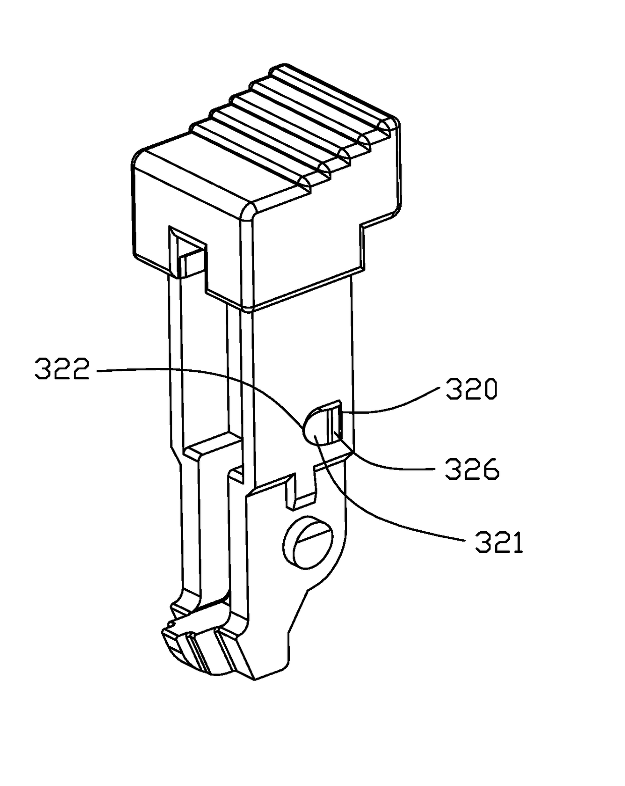
[0015]The insulative housing 10 includes two side walls 11 extending along a longitudinal direction and two tower-shaped portions 13 protruding upwardly from two opposite ends of the side walls 11, respectively. The insulative housing 10 includes a central slot 12 defined between the side walls 11 to receive the card module 200. Each of the tower-shaped portions 13 includes a mounting slot 14 to receive the corresponding ejector 30. The ejector 30 is pivotally mounted in the mounting slot 14. The ejector 30 includes a main portion 31 and two holding portions 32 each protrudi...


PUM


Abstract

A card edge connector includes an insulative housing along a longitudinal direction, a number of terminals fixed in the insulative housing and an ejector pivotally mounted to the insulative housing. The insulative housing has two side walls and a number of tower-shaped portions protruding upwardly from the side walls. The insulative housing has a central slot between two side walls. The tower-shaped portion has a mounting slot. The tower-shaped portion defines a holding recess communicated to the mounting slot. The ejector has a main portion and a number of holding portions protruding from two opposite sides of the main portion. The holding portion has a first portion and a second portion extending from the first portion. The first portion is closer to the central slot than the second portion. The first portion has a front edge with a sleek section.

Description

FIELD OF THE DISCLOSURE[0001]The invention is related to a card edge connector, and particularly to a latch structure of the card edge connector.DESCRIPTION OF RELATED ARTS[0002]Chinese Utility Patent No. 204243352U discloses a card edge connector including an insulative housing, a plurality of terminals received in the insulative housing and an ejector. The insulative housing includes a longitudinal body and two tower-shaped portions located at two opposite ends of the body. The tower-shaped portion is perpendicular to the body. The body defines a slot extending to the tower-shaped portion. The terminals are arranged at two side walls of the slot and each of which includes a contact portion extending into the slot. The ejector includes a long arm mounted in the tower-shaped portion and an operating head. The ejector rotates outward around the tower-shaped portion when an external force is working on the operating head. The long arm has a protrusion latched in the tower-shaped porti...

Claims


Application Information

Patent Timeline
IPC IPC(8): H01R12/70H01R12/72G06F1/18
CPCH01R12/7029H01R12/721G06F1/18H05K7/1409
Inventor BU, XUE-WUTANG, WEN-JUNLI, ZHUANG-XINGZHANG, JIAN
Owner FOXCONN INTERCONNECT TECHNOLOGY LIMITED
Features
  • R&D
  • Intellectual Property
  • Life Sciences
  • Materials
  • Tech Scout
  • Unparalleled Data Quality
  • Higher Quality Content
  • 60% Fewer Hallucinations
Learn More