Unidirectional valve for presurized containers

a technology for presurizing containers and valves, which is applied in the direction of feeding bottles, teasers, etc., can solve the problems of limited vacuum build-up inside the bottle, and cannot be fully recommended for inflatable use, and achieve the effect of preventing undesired leakage from the container

Inactive Publication Date: 2018-10-04
VASERMAN ELCHANAN
View PDF0 Cites 0 Cited by
  • Summary
  • Abstract
  • Description
  • Claims
  • Application Information

AI Technical Summary

Benefits of technology

[0003]In a first broad aspect the invention relates to the recognition of a most appropriate valve type for use in baby feeding devices of the type comprising inflatable container. In this regard it is suggested by the inventor of the present invention that inclusion of an oppositely oriented unidirectional valve in the liquid outlet of a baby feeding device of the type comprising inflatable container is the most advantageous way for preventing undesired leaks from the container.
[0005]A main advantage of such valve once put to use in an inflatable container e.g. of the type suggested by WO2006129302 is that the liquid pressure exerted on the liquid content by the balloon-like stretched wall will tend to close the valve thus securing it against leakage better than what provided by any of the three valve arrangements originally suggested by said document, arrangements in which the internal liquid pressure tends to open the valve.
[0007]The problems associated with unidirectional valves based on the aforementioned types when used in inflatable containers are solved by a second aspect of the invention, relating to a nipple for baby feeding containers, the nipple comprising a unidirectional valve oriented with a convexity of a deformable curved wall thereof (e.g. a domed wall or a conic wall) facing the container's hollow, said valve is characterized by at least two non intersecting slits formed in the deformable curved wall, which through said slits liquid can controllably flow. Due to the fact that the slits do not intersect, the valve closure means is flap free, interference between the function of the slits is avoided, and the transformation of each slit from a distorted open state to a normal close state and vise versa is substantially independent of the state of the other slits.

Problems solved by technology

The build-up of vacuum inside the bottle is limited, however, because the valve functions as a unidirectional, allowing entrance of air from outside when the atmospheric pressure is greater than the pressure inside the bottle.
Unfortunately, the valve suggested by U.S. Pat. No. 5,035,340 cannot be fully recommended for use in inflatable containers of the type disclosed by WO2006129302, because the internal liquid pressure in such containers is substantially greater than in the conventional ones towards which the invention of U.S. Pat. No. 5,035,340 is aimed.
Unfortunately, in case the valve of U.S. Pat. No. 5,035,340 is adopted for inflatable container of the type presented by WO2006129302, the pressurized reverse flow forced through the valve by the thrust provided by the inflatable container, and / or the internal liquid pressure maintained in the inflatable container, may prevent one or more of the valve flaps from retracting to its regular undistorted position upon release of the baby's mouth pressure, thus leaving the valve partially open i.e. with one or more of the flaps remaining over bent towards a reverse flow permitting position.

Method used


Image

  • Unidirectional valve for presurized containers
  • Unidirectional valve for presurized containers
  • Unidirectional valve for presurized containers

Examples


Embodiment Construction

[0017]The present invention will be further explained by the accompanying Figures. With specific reference now to the figures in detail, it is stressed that the particulars shown are by way of example and for purposes of illustrative discussion of one or more preferred embodiments of the present invention, and are presented in the cause of providing what believed to be the most useful and readily understood description of the principles and conceptual aspects of the invention. In this regard, no attempt is made to show in the figures structural details of the invention in more detail than necessary for understanding the basics of the invention, the description taken with the drawings making apparent to those skilled in the art how several forms of the invention may be embodied in practice.

BRIEF DESCRIPTION OF THE FIGURES

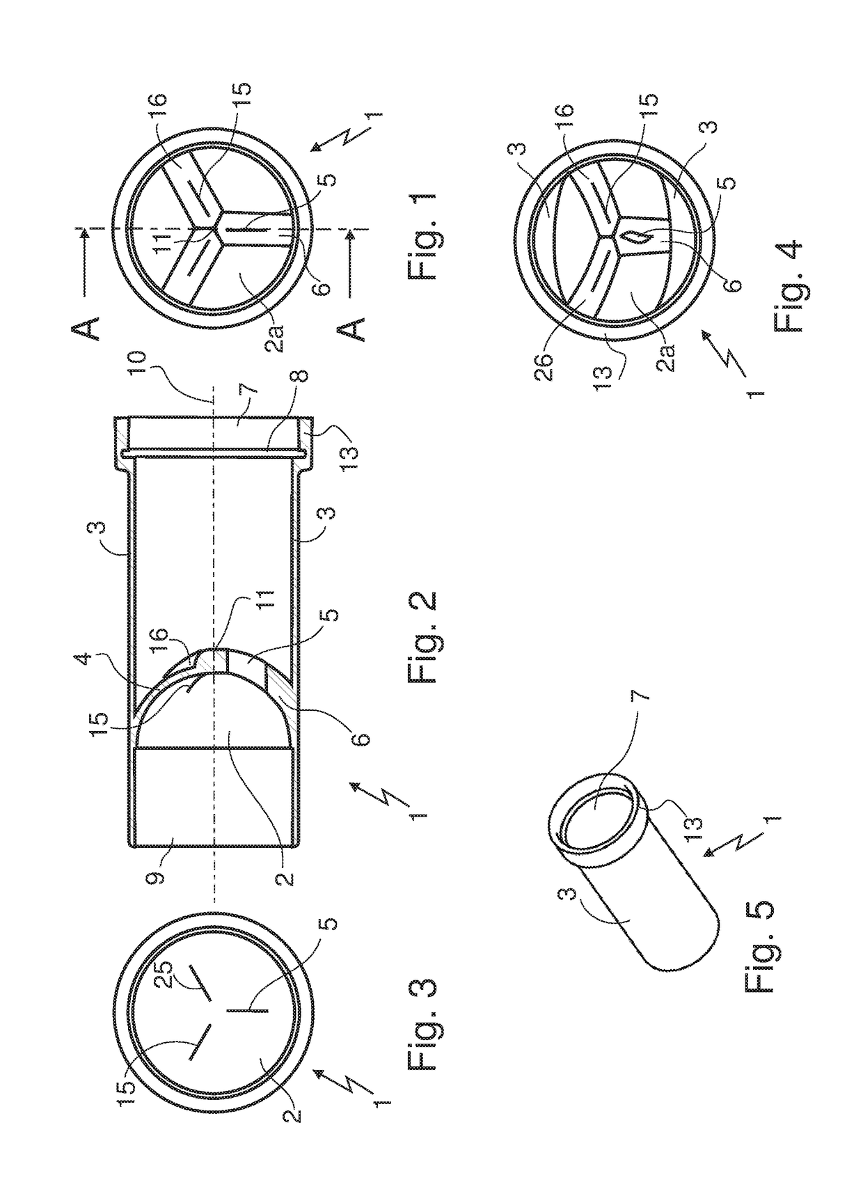
[0018]FIG. 1 illustrates a valved nipple part according to the present invention as seen from its liquid inlet side.

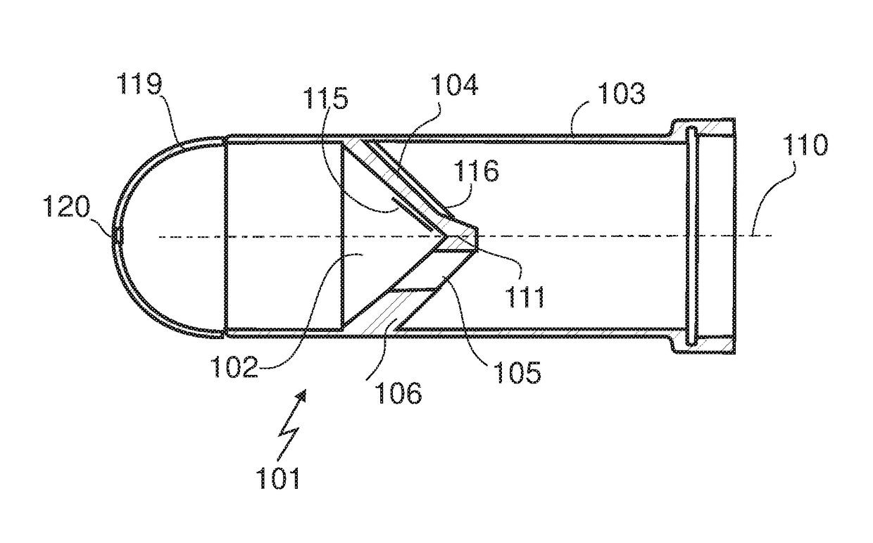
[0019]FIG. 2 illustrates a longitudinal cross sec...


PUM


Abstract

In a nipple for a baby feeding container, a valve part is disclosed, comprising a unidirectional valve formed of a pliable material and oppositely oriented such that when attached to the container a normal fluid flow through the valve is into the container while a flow from the container to the outside is normally blocked, the valve is characterized by a plurality of normally closed non intersecting slits formed in a deformable wall which blocks the flow of liquid from the container to the outside unless when the slits become temporarily distorted by the natural mouth maneuverings of a baby. The valve is especially advantageous for use in baby feeding containers of inflatable type in which the liquid content is pressurized under the pressure exerted by the stretched elastomeric walls of the container.

Description

FIELD OF THE INVENTION[0001]The present invention is in the field of valves for baby feeding devices.BACKGROUND OF THE INVENTION[0002]Baby feeding bottles in use today are in the form of rigid containers made of polymeric materials. They comprise a teat and screw closure over a top opening through which liquid nutrition content can be filled when the closure is taken off. One known problem associated with such bottles is that during the feeding process there is a build up of vacuum inside due to volumes of liquid exiting the bottle for consumption without simultaneously being exchanged by similar volumes of air. This vacuum complicates the feeding process, distracts its continuity and upsets the baby. A number of solutions to this problem have been suggested, one of which is the use of inflatable containers that automatically adapt their volume to the volume of their liquid content, as disclosed by WO2006129302. Elastomeric balloon-like containers as suggested by WO2006129302 requir...

Claims


Application Information

Patent Timeline
Patent Type & Authority Applications(United States)
IPC IPC(8): A61J11/00
CPCA61J11/002A61J11/0015A61J11/0065A61J9/005
Inventor VASERMAN, ELCHANAN
Owner VASERMAN ELCHANAN
Why Eureka
Try Eureka