
Space optimization solver using team collaboration patterns to guide team-to-floor allocation planning

Inactive Publication Date: 2018-10-04
MICROSOFT TECH LICENSING LLC
View PDF26 Cites 4 Cited by
  • Summary
  • Abstract
  • Description
  • Claims
  • Application Information

AI Technical Summary

Benefits of technology

The present technology provides space optimization tools that use social collaboration data to guide team-to-location allocation planning. These tools create a smart location layout that achieves desired business outcomes, such as minimizing employee's commute time to other teams and stimulating collaborations between teams. The tools use a combination of team collaboration patterns and social collaboration data to optimize the allocation of teams and individuals. The technology does not rely on pre-existing layouts and can create a smart location plan automatically. Overall, the technology helps optimize space usage and enhance collaboration within organizations.

Problems solved by technology

These employees are often collocated within the office space, but determining which divisions or teams should sit next to each other can be a difficult task as the company occupies multiple floor and / or multiple buildings.
In many instances the decision on where specific employees, or groups of employees, are physically located may be based on criteria that may not result in more effective collaboration.
As a result, locating employees based on these types of criteria may not result in the optimal entity efficiency and engagement.
Upon reading the following, other limitations of existing or prior systems will become apparent to those of skill in the art.

Method used


Image

  • Space optimization solver using team collaboration patterns to guide team-to-floor allocation planning
  • Space optimization solver using team collaboration patterns to guide team-to-floor allocation planning
  • Space optimization solver using team collaboration patterns to guide team-to-floor allocation planning

Examples


Embodiment Construction

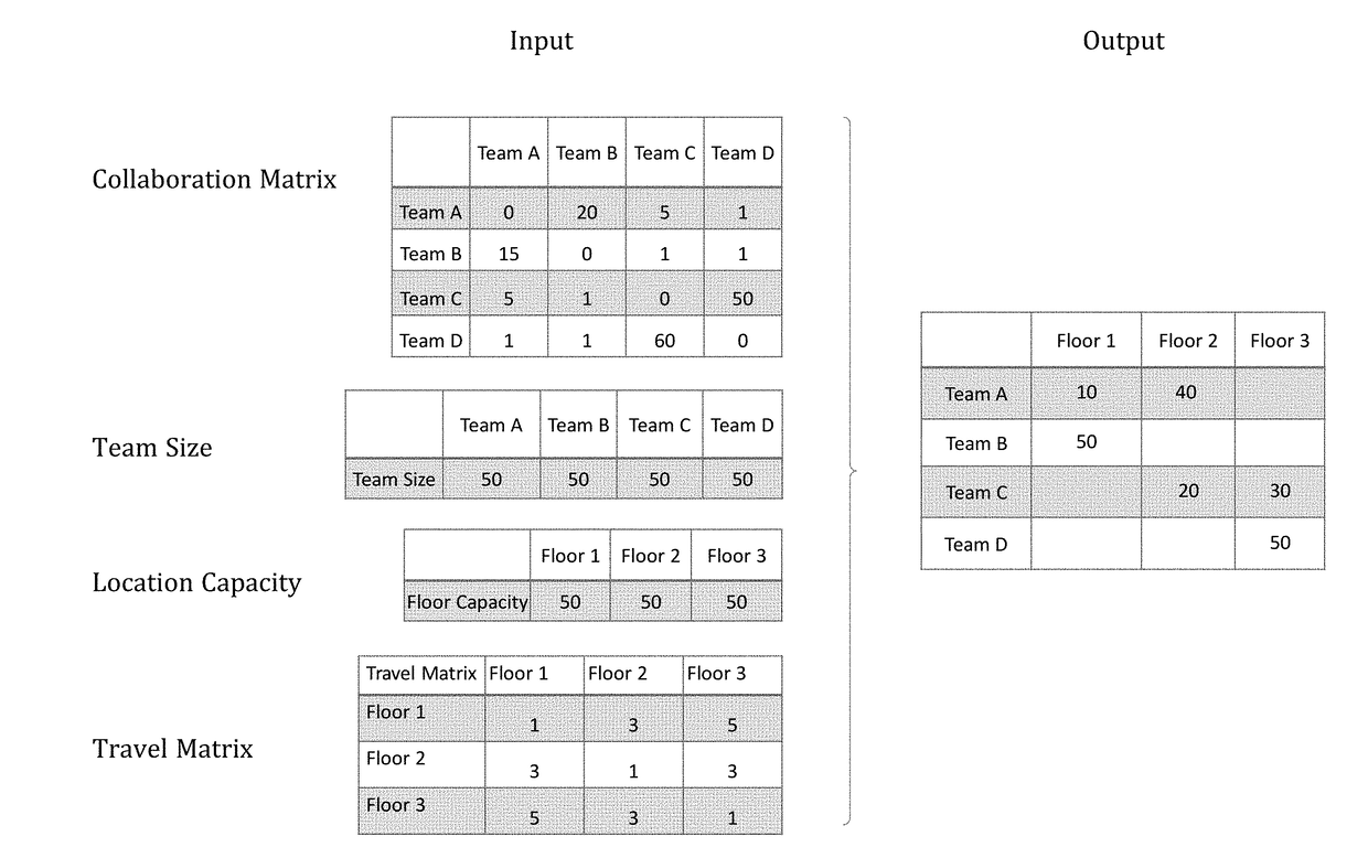
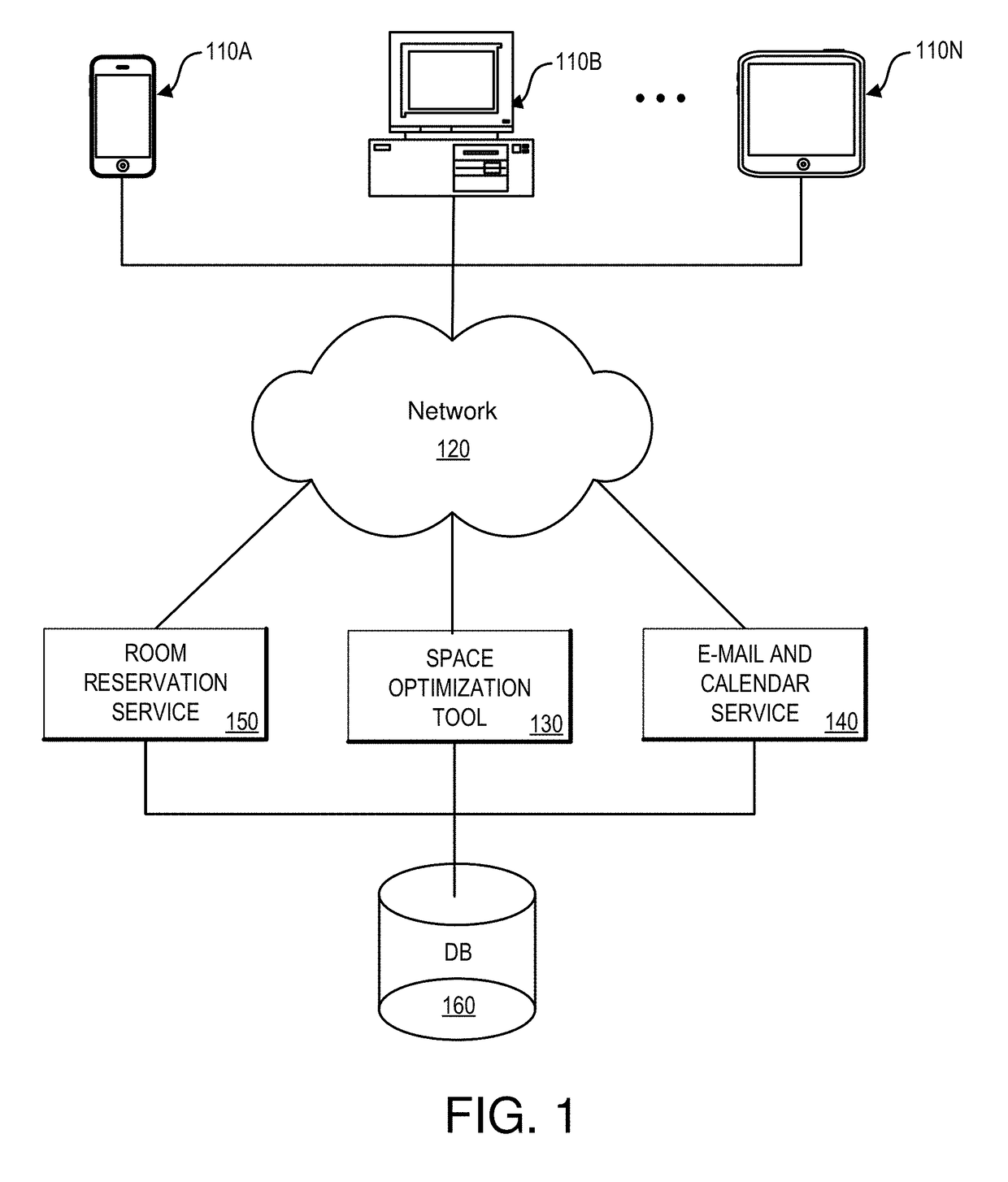
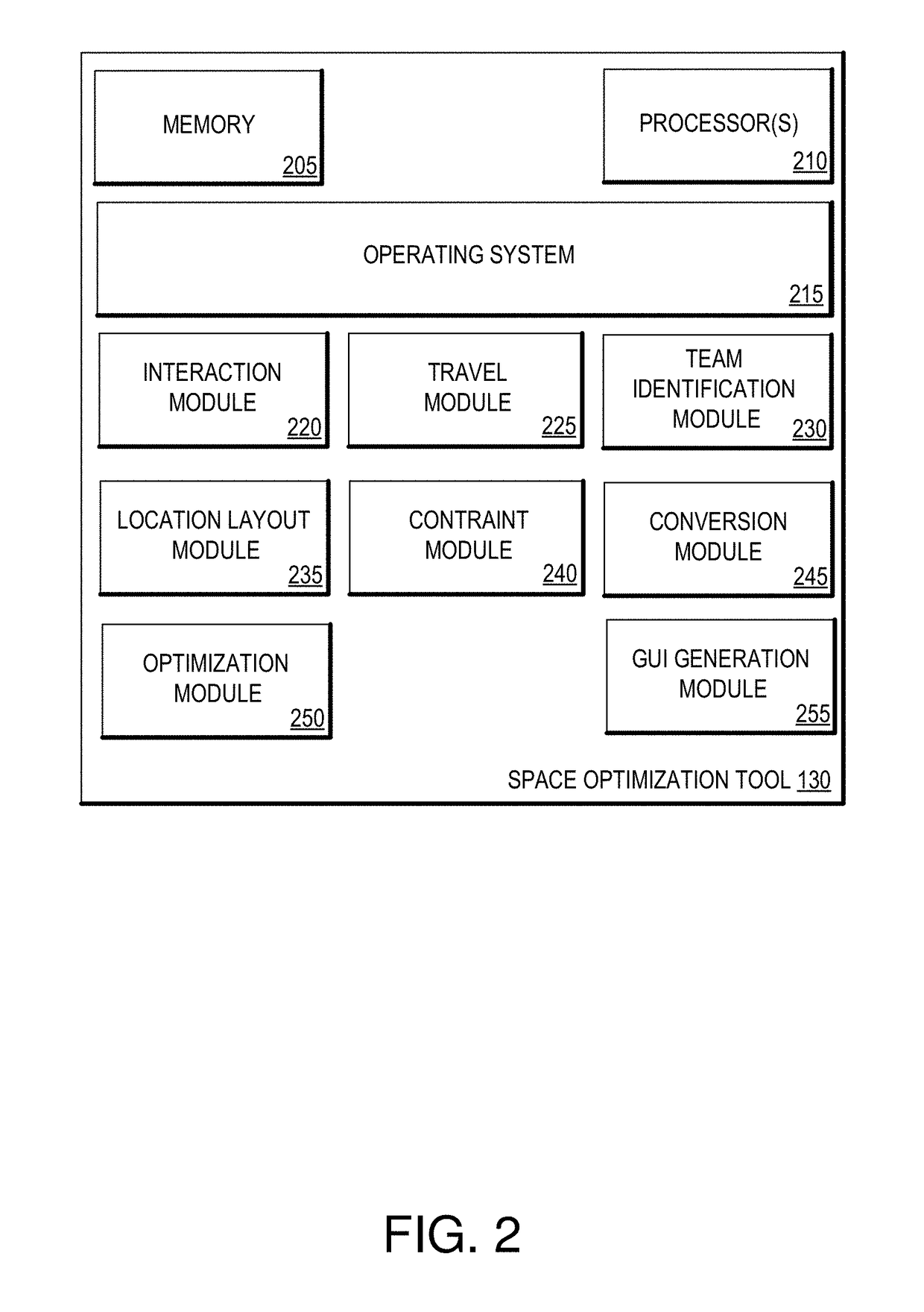
[0019]Various embodiments of the present technology generally relate to space optimization tools. More specifically, some embodiments provide for space optimization tools that use team collaboration patterns to guide team-to-location allocation planning. Some embodiment of the space optimization tool uses social collaboration data that tracks people's communication patterns, such as how frequently teams talk to each other. The social collaboration data can be used to by the space optimization tool to guide how individuals and teams should sit on different locations (e.g., within floors, buildings, team areas, desks, etc.). The space optimization tool can create a smart location layout that achieves desired business outcomes, such as minimizing employee's commute time to other teams, stimulating collaborations between teams, and the like. In accordance with various embodiments, the space optimization tool typically does not rely on the existence of prior layouts, and instead creates ...


PUM


Abstract

Various embodiments of the present technology provide for a space optimization tool. More specifically, some embodiments provide for a space optimization tool that uses team collaboration patterns to guide team-to-location allocation planning. Some embodiments of the space optimization tool use social collaboration data that tracks people's communication patterns, such as how frequently teams talk to each other. The social collaboration data can be used to by the space optimization tool to guide how individuals and teams should sit on different locations (e.g., within floors, buildings, etc.). The space optimization tool can create a smart floor layout that achieves desired business outcomes, such as minimizing employee's commute time to other teams, stimulating collaborations between teams, and the like. In accordance with various embodiments, the space optimization tool can create a smart layout by using an optimization model to automatically optimize a target function at global level.

Description

BACKGROUND[0001]Successful companies of all sizes need employees to work jointly together and collaborate on various projects, designs, and other endeavors. This is true of intellectually based endeavors as well as physically based endeavors. As part of the collaboration process, employees often meet in conference rooms or other collaborative space in order to share ideas, share project goals, share project status and otherwise facilitate portions of the collaboration. For very small companies, all of the employees can easily fit within a small space. As companies grow, however, the employees become more spread out within the same building, multiple buildings within an office complex, and eventually within multiple buildings around the world.[0002]Larger companies often create various divisions or teams of employees to focus on developing knowledge in specific areas. These employees are often collocated within the office space, but determining which divisions or teams should sit nex...

Claims


Application Information

Patent Timeline
IPC IPC(8): G06Q10/06G06F3/0484G06Q10/10
CPCG06Q10/0631G06Q10/109G06F3/04847G06Q10/00
Inventor ASHIKHMIN, ALEKSEYXIAO, LINMENG, SINIELSEN, CHANTRELLE
Owner MICROSOFT TECH LICENSING LLC
Learn More