High temperature furnace

a high-temperature furnace and high-temperature technology, which is applied in the direction of furnaces, furnace types, furnaces, etc., can solve the problems of not having the opportunity to test the reaction of the specimen, the single heating zone provided by the conventional high-temperature furnace may not produce an acceptable temperature gradient profile of the test specimen that is within the testing specifications,

Active Publication Date: 2018-11-01
GENERAL ELECTRIC CO
View PDF11 Cites 1 Cited by
  • Summary
  • Abstract
  • Description
  • Claims
  • Application Information

AI Technical Summary

Benefits of technology

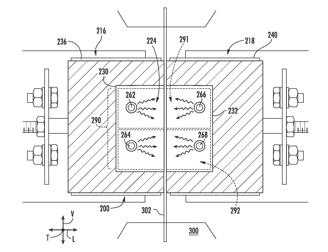
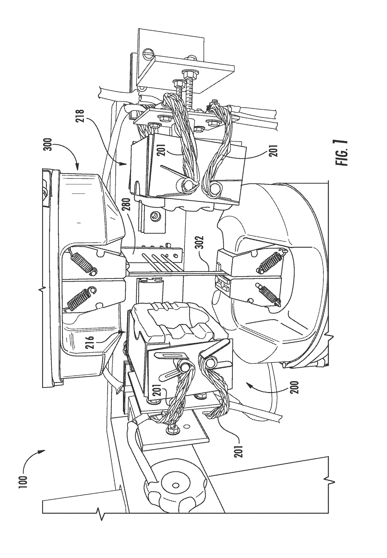
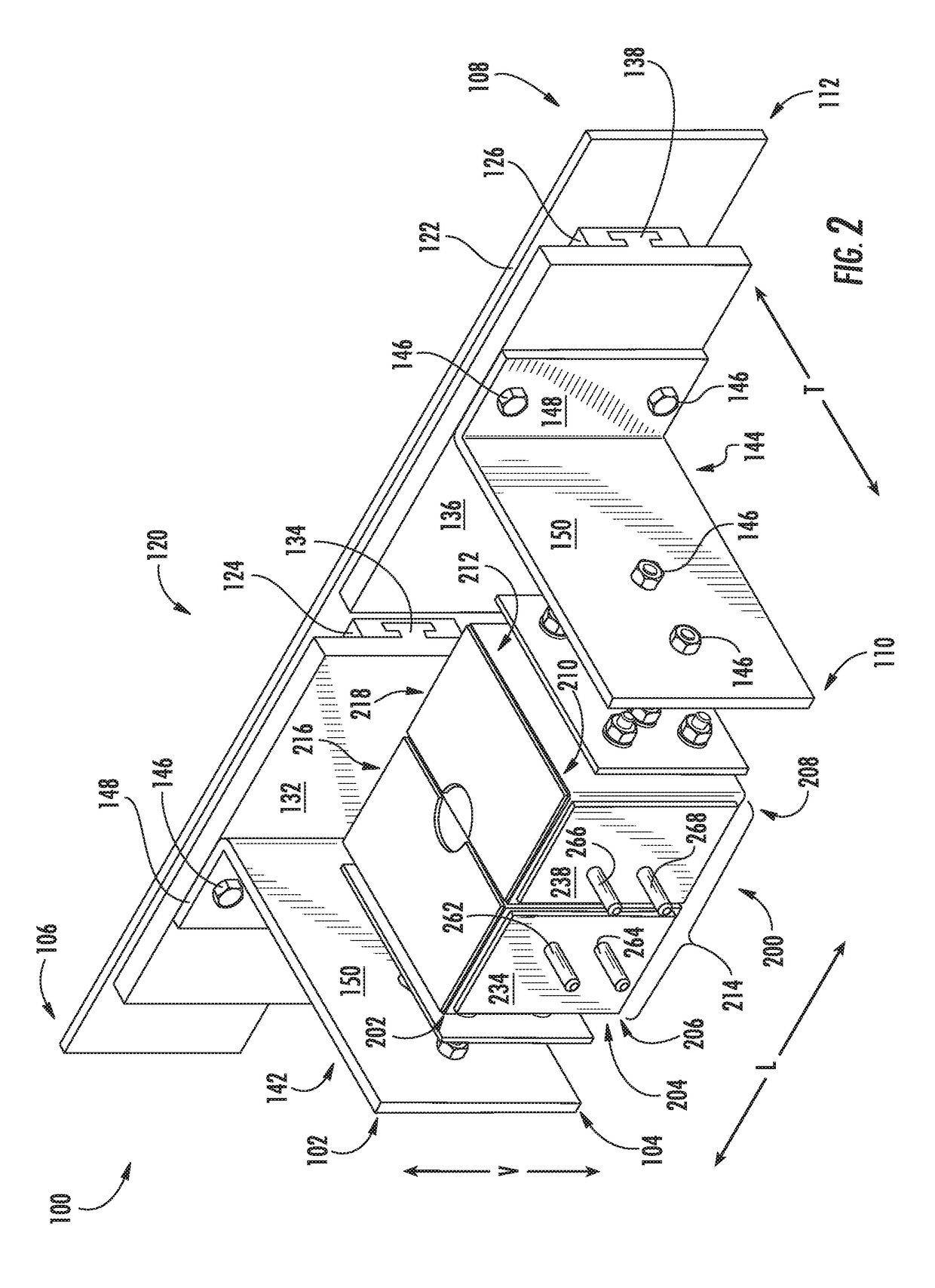
[0007]In one exemplary aspect, the present subject matter is directed to a high temperature furnace. The high temperature furnace defines a vertical direction, a lateral direction, and a transverse direction. The high temperature furnace includes a shell defining a heating chamber. The high temperature furnace also includes a plurality of heating elements each extending at least partially through the heating chamber. The plurality of heating elements include a first top heating element, a first bottom heating element, a second top heating element, and a second bottom heating element. The first top heating element is spaced apart from the second top heating element along the lateral direction. The first bottom heating element is spaced apart from the second bottom heating element along the lateral direction. The first and second top heating elements are spaced apart from the first and second bottom heating elements along the vertical direction. During operation of the high temperature furnace, the heating elements define at least two heating zones, including a first heating zone and a second heating zone.

Problems solved by technology

However, such conventional high temperature furnaces tend to fail when operated at high temperatures during prolonged operating periods, such as e.g., when heating a CMC specimen for the duration of a run-out strain controlled fatigue test.
Thus, there is no opportunity to test how the specimen will react when subjected to multiple heating zones.
Furthermore, the single heating zone provided by conventional high temperatures furnaces may not produce an acceptable temperature gradient profile of the test specimen that is within testing specifications.
Moreover, in an attempt to maintain the set point temperature within the heating chamber of such conventional furnaces, large amounts of current are passed through the heating elements, which negatively impacts the energy efficiency of the furnace and disrupts testing instrumentation.
Additionally, the heating elements of conventional furnaces are oriented and configured in such a way (e.g., U-shaped heating elements) that they effectively increase the size of the furnace, making the high temperature furnace assembly bulky and more costly.

Method used


Image

  • High temperature furnace
  • High temperature furnace
  • High temperature furnace

Examples


Embodiment Construction

[0028]Reference now will be made in detail to embodiments of the invention, one or more examples of which are illustrated in the drawings. Each example is provided by way of explanation of the invention, not limitation of the invention. In fact, it will be apparent to those skilled in the art that various modifications and variations can be made in the present invention without departing from the scope or spirit of the invention. For instance, features illustrated or described as part of one embodiment can be used with another embodiment to yield a still further embodiment. Thus, it is intended that the present invention covers such modifications and variations as come within the scope of the appended claims and their equivalents.

[0029]As used herein, the terms “first”, “second”, and “third” may be used interchangeably to distinguish one component from another and are not intended to signify location or importance of the individual components.

[0030]The present subject matter is dire...


PUM


Abstract

A high temperature furnace includes features that provide for multiple heating zones for heating a specimen extending at least partially through a heating chamber defined by the furnace. In one exemplary aspect, the furnace can include multiple heating elements extending at least partially through the heating chamber. Each heating element can be configured in a rod shape, which allows for multiple heating zone capability, better control over the temperature gradient, reduced current to achieve a desired temperature output, and a streamlined furnace shell.

Description

FIELD[0001]The present subject matter is generally related to high temperature furnaces.BACKGROUND[0002]Generally, there is a need to heat specimens to high temperatures for testing and analytical purposes, among other possible reasons. For instance, during a strain controlled fatigue test, a specimen can be heated to temperatures at or exceeding 2400° F. by a high temperature furnace. In some cases, such as when testing a specimen formed of a Ceramic Matrix Composite (CMC) material, it is desirable to heat the CMC specimen to temperatures at or exceeding 2700° F. It may likewise be desirable to heat other materials having high temperature capability to high temperatures.[0003]Conventional high temperature furnaces used to heat such specimens are typically capable of reaching high temperatures. However, such conventional high temperature furnaces tend to fail when operated at high temperatures during prolonged operating periods, such as e.g., when heating a CMC specimen for the dura...

Claims


Application Information

Patent Timeline
Patent Type & Authority Applications(United States)
IPC IPC(8): F27D11/12F27B17/00
CPCF27D11/12F27D2099/0011F27B2017/0091F27B17/0016F27B9/06F27B9/28F27D11/00F27D19/00F27D21/00
Inventor WALLACE, MARCUS NATHANIALSEITHER, ROGER IRVIN
Owner GENERAL ELECTRIC CO
Why Eureka
Try Eureka