Attachment device allowing natural wrist rotation for osseointegrated prostheses

Active Publication Date: 2018-11-15
INTEGRUM
View PDF0 Cites 2 Cited by
  • Summary
  • Abstract
  • Description
  • Claims
  • Application Information

AI Technical Summary

Benefits of technology

[0014]A further advantage of the present invention is that the attachment device allows movement of the two bones in relation to each other in all directions, i.e. movement in the xy-plane by means of the first holder being movable in an x-direction together with the individual rotation of the holder. This together with the individual tiltability and individual z translation provides a flexible and modular attachment device which can accommodate a wide range of bone configurations. Moreover, the attachment device is easy to manufacture and reliable, thereby increasing the availability while reducing the cost. Accordingly, the attachment device allows a natural wrist rotation for osseointegrated prostheses.
[0015]The base plate may comprise at least one side wall extending in the z-direction and arranged to prevent said movement of said first holder in an y-direction and to prevent movement of said second holder in said x-direction and in said y-direction. The base plate may comprise one or more continuous, semi-continuous or discrete sidewalls arranged to limit the movement of the holder in the xy-plane. In an example embodiment, the base plate may be a rectangular plate having four sidewalls at the edges of the plate and a sidewall dividing the base plate into two portions where the first holder is arranged in a first portion with sidewalls preventing movement in the x-direction while allowing movement of the holder in the y-direction in relation to the base plate. The second holder is then arranged in a second portion where movement is prevented in both the x- and y-direction. However, the second holder is still allowed to rotate, move in the z-direction and tilt.
[0016]According to one embodiment of the invention, the flexible member may be a flexible mat covering the base plate, and arranged between the holders and the base plate to allow a movement in the z-direction of the holder as well as a tilting motion and rotation. However, the flexible member may also be a gasket or the like, or a flexible mat divided into several portions for example depending on the arrangement of side walls on the base plate.
[0017]In one embodiment of the invention, the attachment device according may further comprise a slider element arranged between a portion of the first holder and the flexible member, wherein the slider element is selected from a material such that the first holder may move in the x-direction by sliding on the slider element. Depending on the choice of material and configuration of the flexible member, it may be desirable to use a slider element arranged between a contact surface of the holder and a corresponding contact surface of the flexible member to ensure that the friction is

Problems solved by technology

Although prosthetic limbs have been around for centuries, several problems are often experienced by amputees making use of a traditional socket attachment.
However, in cases where the flexible member is a flexible mat made from a rubber-like material, the friction between the flexible mat and the holder may prevent the desired movement.
Additionally, when using a slider elem

Method used


Image

  • Attachment device allowing natural wrist rotation for osseointegrated prostheses
  • Attachment device allowing natural wrist rotation for osseointegrated prostheses
  • Attachment device allowing natural wrist rotation for osseointegrated prostheses

Examples


Example

[0040]In the present detailed description, various embodiments of the system and method according to the present invention are mainly described with reference to an attachment device comprising a rectangular base plate. However, it should be noted that the base plate may equally well have other shapes, such as circular, elliptical etc.

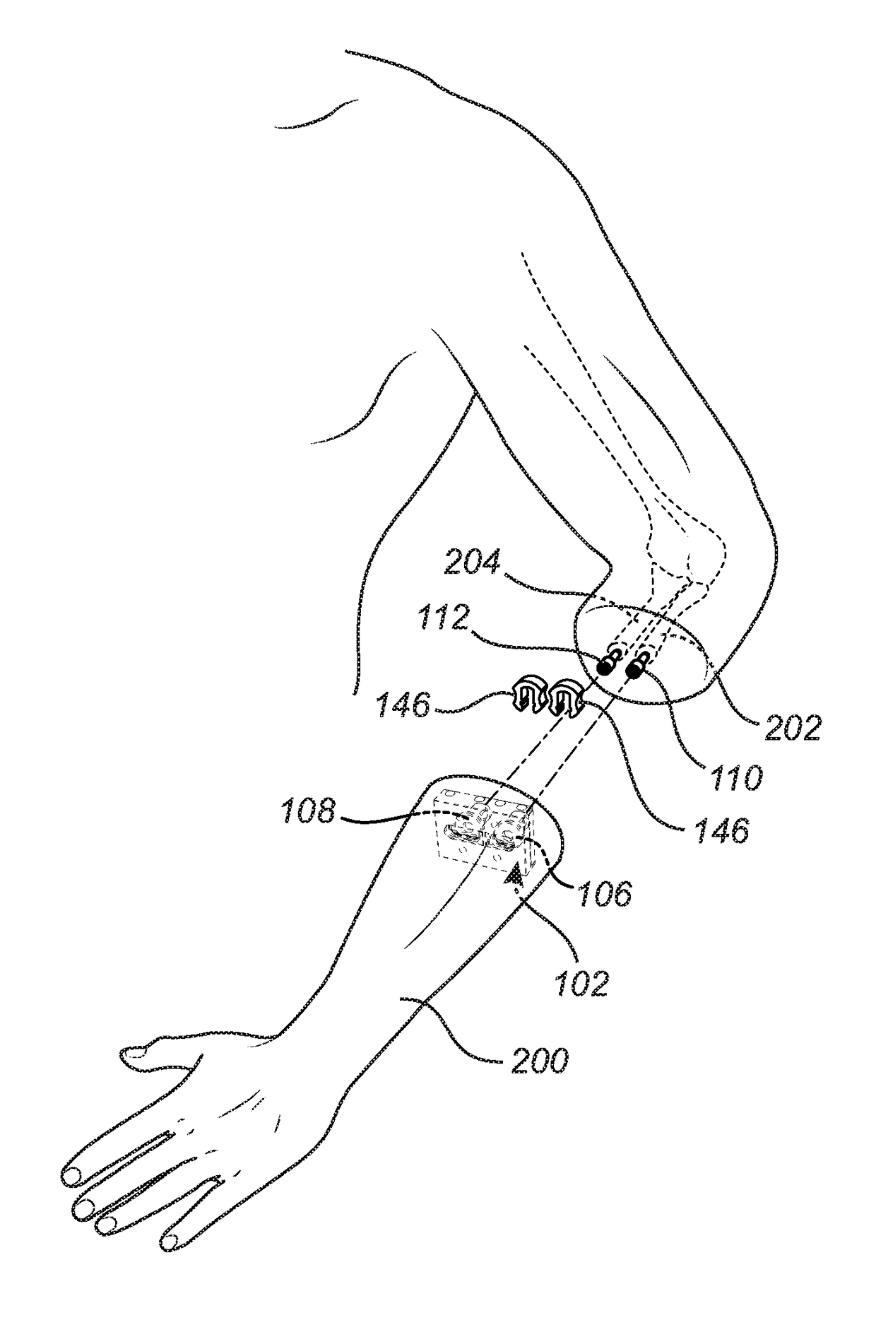
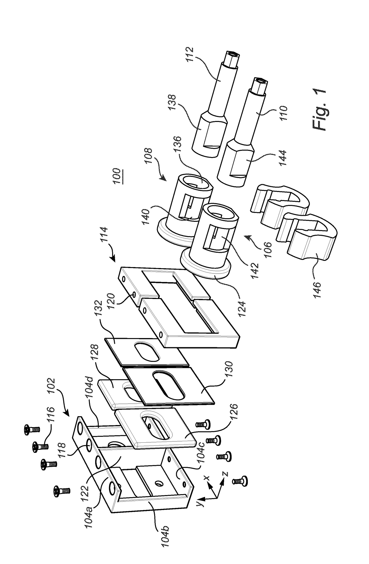
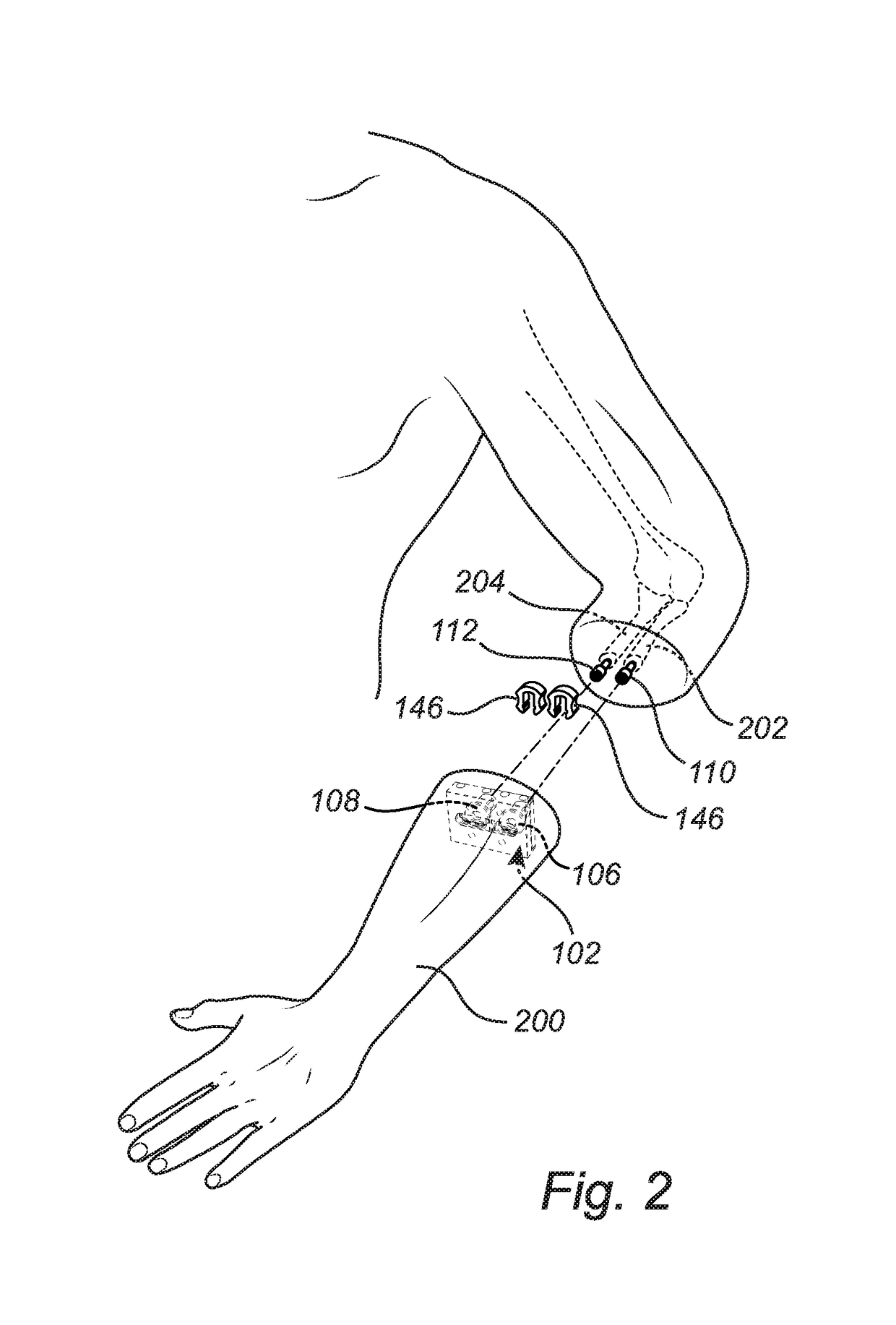
[0041]FIG. 1 schematically illustrates an attachment device 100 for attaching a prosthesis to implants in a stump. The attachment device 100 comprises a base plate 102 having an extension in an xy-plane, where the xy-plane is defined as the base plane of the base plate 102. The base plate 102 comprises four side walls 104a-d, extending in the z-direction perpendicular to the base plate 102. The attachment further comprises a first and a second holder 106, 108 for holding a corresponding first and second abutment 110, 112. In use, the abutments will be implanted into a bone of an amputee, such that the attachment device 100 acts as an intermediate eleme...


PUM


Abstract

The present invention relates to a an attachment device for attaching a prosthesis to a bone, comprising: a base plate having an extension in an xy-plane; a first holder for holding a first abutment; a second holder for holding a second abutment; a locking plate attached to the base plate to restrict movement of the holders in a z-direction away from the base plate. The locking plate is configured to allow rotation of the first and second holder around a z-axis perpendicular to the xy-plane. The locking plate and the base plate is configured to allow movement of the first holder along the x-direction and to prevent movement the y-direction and to prevent movement of the second holder in the x-and y-direction. At least one flexible member is arranged between each of the first and second holders and the base plate, the flexible member being flexiblein the z-direction to allow movement of the first and second holder in the z-direction and to allow the first and second holder to tilt with respect to the xy-plane.

Description

FIELD OF THE INVENTION[0001]The present invention relates to an attachment device for a prosthetic limb. In particular, the preset invention relates to an attachment device for attaching a prosthetic device to implants in the radius bone and in the ulna bone.BACKGROUND OF THE INVENTION[0002]Although prosthetic limbs have been around for centuries, several problems are often experienced by amputees making use of a traditional socket attachment. These include but are not limited to: dermatological problems, and a limited range of motion. A prosthesis that does not clamp around the residual limb of the amputee but is anchored directly to the skeleton avoids socket-related problems and improves prosthesis use and quality of life substantially.[0003]A way in which this is achieved is through osseointegration, which is described as a permanent integration between bone and a titanium implant. An extension component from the implant protrudes the skin of the patient and can be connected to ...

Claims


Application Information

Patent Timeline
IPC IPC(8): A61F2/58A61F2/78
CPCA61F2/583A61F2/78A61F2002/543A61F2002/7887A61F2/68A61F2002/5007A61F2002/6854A61F2/54
Inventor ORTIZ CATALAN, MAX JAIRMILLENAAR, JASON
Owner INTEGRUM
Why Eureka
Try Eureka