Image forming apparatus having optical print head
a technology of optical print head and image forming apparatus, which is applied in the direction of electrographic process apparatus, optics, instruments, etc., can solve the problems of deteriorating image quality of output images, damage to the surface of photosensitive drum and lenses, and contamination of light emission faces of lenses with optical print heads
- Summary
- Abstract
- Description
- Claims
- Application Information
AI Technical Summary
Benefits of technology
Problems solved by technology
Method used
Image

Examples
embodiment
Image Forming Apparatus
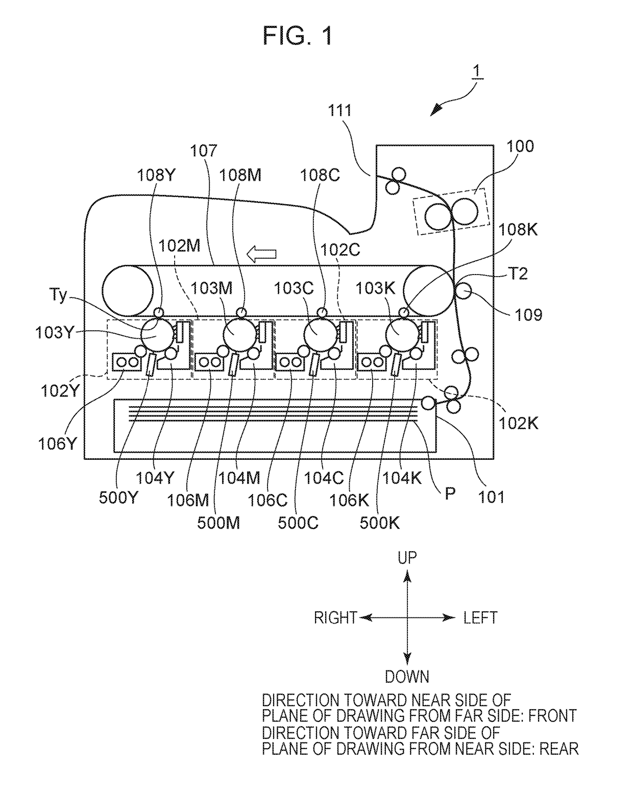
[0039]First, a schematic configuration of an image forming apparatus 1 will be described. FIG. 1 is a schematic cross-sectional view of the image forming apparatus 1. Although the image forming apparatus 1 illustrated in FIG. 1 is a color printer (small function printer (SFP)) that does not have a reader, an embodiment may be a copying machine that has a reader. Also, an embodiment is not restricted to a color image forming apparatus having multiple photosensitive drums 103 as illustrated in FIG. 1, and may be a color image forming apparatus having one photosensitive drum 103 or an image forming apparatus that forms monochromatic images.
[0040]The image forming apparatus 1 illustrated in FIG. 1 has four image forming units 102Y, 102M, 102C, and 102K (hereinafter also collectively referred to simply as “image forming unit 102”) that form toner images of the yellow, magenta, cyan, and black colors. The image forming units 102Y, 102M, 102C, and 102K respectively h...
first modification
[0175]The mechanism bringing the optical print head 105 to the retracted position (cleaning position) is not restricted to the above-described mechanism where the holding member 505 comes into contact with the first seating face 586 and second seating face 587 described earlier, thereby restricting downward movement of the holding member 505. A mechanism such as described next may be made.
[0176]FIG. 29A1 illustrates a structure using the slot 691, which is an elongated opening provided to the sliding portion 525, as an example of an abutted portion (stopping mechanism). The mechanism illustrated in FIG. 29A1 is a mechanism that stops sliding movement of the sliding portion 525 that moves by sliding along with movement of the optical print head 105 from the exposure position toward the retracted position, thereby bringing the optical print head 105 to the retracted position. The sliding portion 525 in FIG. 29A1 has the slot 691. The slot 691 has an abutting portion 591. Out of the ed...
second modification
[0180]The mechanism bringing the optical print head 105 to the retracted position may be a mechanism where pivoting of the link member 651 serving as an example of a link portion is stopped using an abutting member 982 as an example of the abutted portion (stopping mechanism), as illustrated in FIG. 29B. This mechanism will be described in detail with reference to FIG. 29B. FIG. 29B is a diagram for describing the abutted portion (stopping mechanism) according to the second modification.
[0181]The abutting member 982 serving as an example of the abutted portion (stopping mechanism) is fixed to the third support portion 526 as illustrated in FIG. 29B. The abutting member 982 is, for example, a cylindrical protrusion, erected on the sliding portion 525 side at the third support portion 526. The abutting member 982 is disposed facing the bearing 610 that the link member 651 has, on the rotational axis of the photosensitive drum 103. When the bearing 610 that the link member 651 has abut...
PUM
 Abstract
Description
Claims
Application Information
 - R&D
- Intellectual Property
- Life Sciences
- Materials
- Tech Scout
- Unparalleled Data Quality
- Higher Quality Content
- 60% Fewer Hallucinations
Browse by: Latest US Patents, China's latest patents, Technical Efficacy Thesaurus, Application Domain, Technology Topic, Popular Technical Reports.
© 2025 PatSnap. All rights reserved.Legal|Privacy policy|Modern Slavery Act Transparency Statement|Sitemap|About US| Contact US: help@patsnap.com