Image forming apparatus

Inactive Publication Date: 2019-01-10
CANON KK
View PDF1 Cites 0 Cited by
  • Summary
  • Abstract
  • Description
  • Claims
  • Application Information

AI Technical Summary

Benefits of technology

The present invention provides an image forming apparatus with an intermediary transfer member that can move in both directions and an executing portion that can execute a supplying operation, a stopping operation, and a reversely moving operation. The executing portion can determine whether or not the supplying operation is executed and will execute the appropriate operation accordingly. This allows for efficient cleaning and maintenance of the image forming apparatus.

Problems solved by technology

In an image forming apparatus using the cleaning blade, a foreign matter such as the paper powder is sandwiched (nipped) between a free end of the cleaning blade and the image bearing member and thus a cleaning performance lowers, so that improper cleaning generates in some cases.
For example, in the case where formation of an image in a high-temperature environment or with a low image ratio (print ratio) is continued, the toner in a developing device deteriorates in some cases.
Further, in the case where the formation of the image in the high-temperature environment or with the low image ratio (print ratio) is continued, a frictional force between the image bearing member and the cleaning blade increases in some instances.
A situation that the supplying operation of the toner to the contact portion between the image bearing member and the cleaning blade is performed after the end of the image formation is also a situation such that the inconveniences such as the turning-up of the cleaning blade is liable to occur.
For that reason, as described above, in the case where the frictional force between the image bearing member and the cleaning blade increases when the subsequent normal rotation of the image bearing member is started, the inconveniences such as the turning-up occur in some instances.
For that reason, there is a liability that the inconveniences such as the turning-up of the cleaning blade occurs.

Method used


Image

  • Image forming apparatus
  • Image forming apparatus
  • Image forming apparatus

Examples


embodiment 1

1. General Constitution and Operation of Image Forming Apparatus

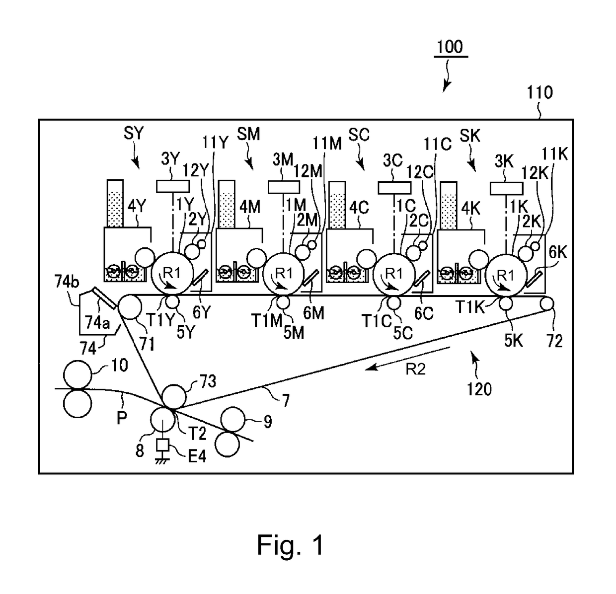
[0020]FIG. 1 is a schematic sectional view of an image forming apparatus 100 in this embodiment according to the present invention.

[0021]The image forming apparatus 100 in this embodiment is a tandem-type (in-line-type) multi-function machine which has functions of a copying machine, a printer and a facsimile machine and which employs an intermediary transfer type capable of forming a full-color image by using an electrophotographic type.

[0022]The image forming apparatus 100 includes, as a plurality of image forming portions, first to fourth image forming portions SY, SM, SC and SK for forming images of yellow (Y), magenta (M), cyan (C) and black (K), respectively. Incidentally, elements having the same or corresponding functions and constitutions in the respective image forming portions SY, SM, SC and SK are collectively described by omitting suffixes Y, M, C and K for representing elements for associated colors in som...


PUM


Abstract

An image forming apparatus includes a photosensitive member, an intermediary transfer member, an image forming portion, a cleaning blade, a motor, and an executing portion capable of executing an operation in an operating mode after an end of the image formation. In the operation in the operating mode, the executing portion is capable of executing a toner supplying operation, a stopping operation of the intermediary transfer member moving in the normal direction, and a reversely moving operation in which the intermediary transfer member is moved in an opposite direction to a normal direction and then is stopped. When the supplying operation is not executed, after an end of the image formation, the stopping operation is executed and then the reversely moving operation is executed. When the supplying operation is executed, after the supplying operation is carried out, the stopping operation is executed but the reversely moving operation is not executed.

Description

FIELD OF THE INVENTION AND RELATED ART[0001]The present invention relates to an image forming apparatus, such as a copying machine, a facsimile machine or a printer, of an electrophotographic type, or an electrostatic recording type.[0002]In the image forming apparatus of the electrophotographic type or the like, a deposited matter such as toner (transfer residual toner) or paper powder on an image bearing member such as a photosensitive member (electrophotographic photosensitive member) has been removed by a cleaning means. As the cleaning means, a cleaning blade which is a cleaning member contacting the image bearing member has been widely used.[0003]In an image forming apparatus using the cleaning blade, a foreign matter such as the paper powder is sandwiched (nipped) between a free end of the cleaning blade and the image bearing member and thus a cleaning performance lowers, so that improper cleaning generates in some cases. Therefore, in Japanese Laid-Open Patent Application (J...

Claims


Application Information

Patent Timeline
IPC IPC(8): G03G15/20G03G21/16G03G21/00G03G15/00
CPCG03G15/205G03G21/169G03G2221/0005G03G15/5008G03G21/0017
Inventor TOMINE, JUN
Owner CANON KK
Why Eureka
Try Eureka