Portable electronic apparatus

Active Publication Date: 2019-02-14
SEIKO EPSON CORP
View PDF5 Cites 2 Cited by
  • Summary
  • Abstract
  • Description
  • Claims
  • Application Information

AI Technical Summary

Benefits of technology

The patent describes a design for a solar cell device that includes an antenna and processing section connected through a connection section. The connection section is positioned overlapping the solar cell in the planar view, which allows for more flexibility in arranging the antenna and processing section. This design also allows for a more compact arrangement of the components, increasing the light receiving area of the solar cell and production of electricity. Additionally, the design includes the use of a nonconductive member and a circuit board as the dielectric body, which further increases the flexibility of the antenna arrangement and improves its receiving sensitivity. Overall, the design provides a more efficient and flexible arrangement for a solar cell device with improved functionality and performance.

Problems solved by technology

With respect to the analog wristwatch disclosed in Document 1, in the case in which such a patch antenna is used in a so-called digital display-type portable electronic apparatus performing digital display using a display panel, there is a problem that the portable electronic apparatus grows in size since the patch antenna is too large in size in the case of installing the display panel, the GPS function, the solar panel, or a variety of sensors.

Method used


Image

  • Portable electronic apparatus
  • Portable electronic apparatus
  • Portable electronic apparatus

Examples


first embodiment

3. Wrist Device

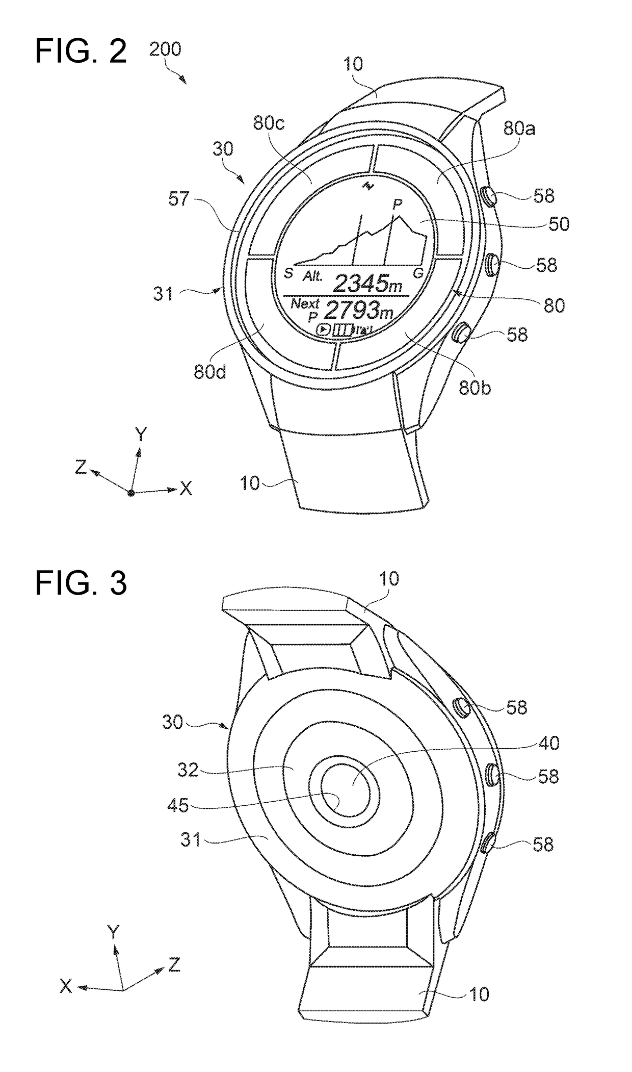
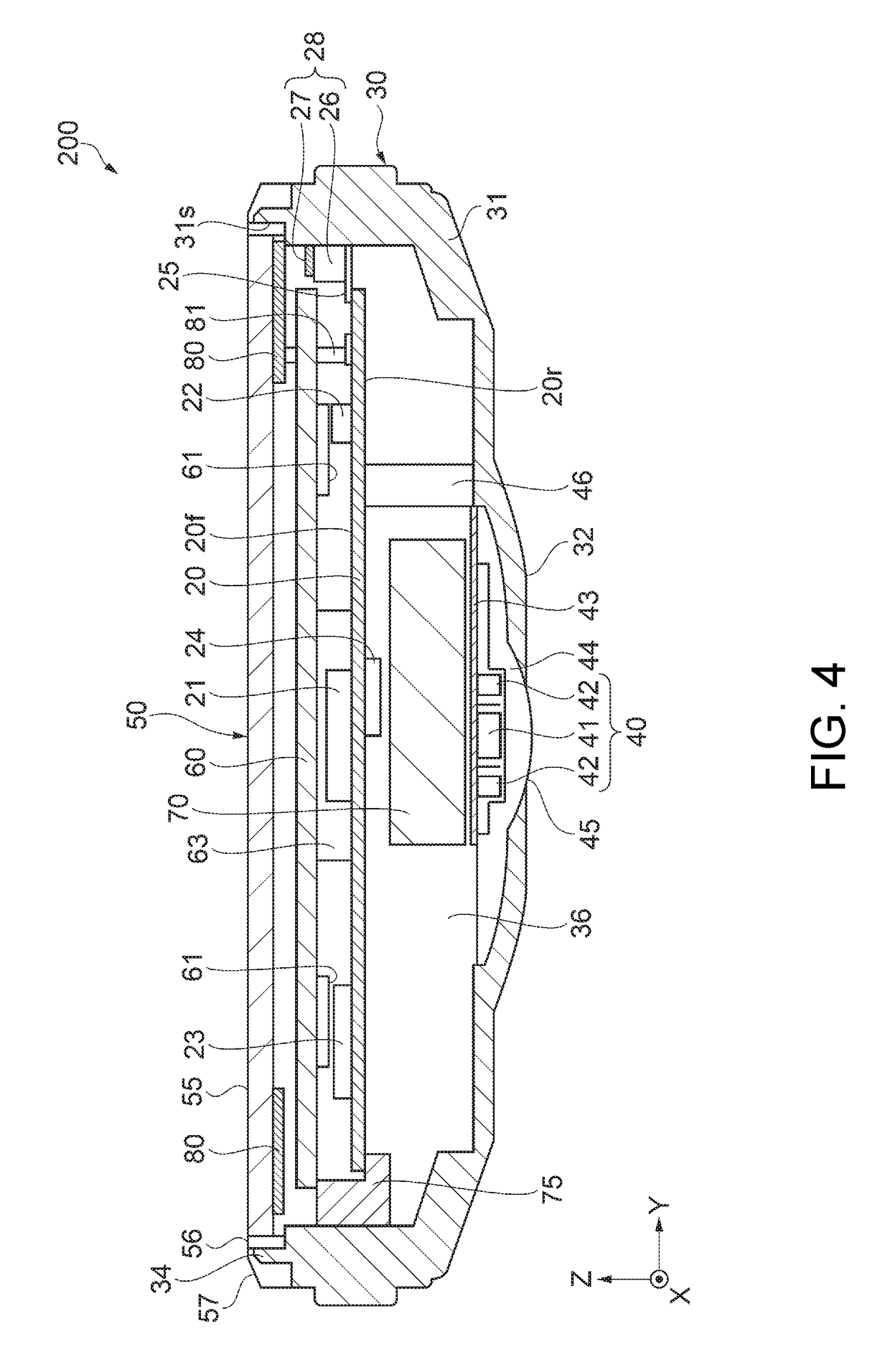
[0056]Then, a configuration of the wrist device (a measurement device) as the portable electronic apparatus according to the first embodiment will be described with reference to FIG. 2, FIG. 3, FIG. 4, FIG. 5, FIG. 6, FIG. 7 and FIG. 8. FIG. 2 is an external perspective view viewed from the obverse side (a display surface side) showing a schematic configuration of the wrist device according to the first embodiment. FIG. 3 is an external perspective view viewed from the reverse side showing the schematic configuration of the wrist device according to the first embodiment. FIG. 4 is a cross-sectional view showing a configuration of the wrist device according to the first embodiment. FIG. 5 is a plan view showing the configuration of the wrist device according to the first embodiment. FIG. 6 is a functional block diagram showing a schematic configuration of the wrist device according to the first embodiment. FIG. 7 is a partial cross-sectional view showing Arrangement Ex...

second embodiment

4. Wrist Device

[0105]Then, a configuration of a wrist device (a measurement device) as the portable electronic apparatus according to a second embodiment will be described with reference to FIG. 9. FIG. 9 is a cross-sectional view showing a configuration of the wrist device according to the second embodiment. FIG. 10 is a plan view showing the configuration of the wrist device according to the second embodiment. It should be noted that in the following description related to the second embodiment, the description will be presented with a focus on the configuration different from that of the first embodiment described above, and substantially the same configuration will be denoted by the same reference numerals in each of the drawings, and the description thereof will be omitted in some cases.

[0106]The wrist device 200A according to the second embodiment shown in FIG. 9 and FIG. 10 is different from the wrist device 200 according to the first embodiment described above in the configu...

modified example 1

[0116]Firstly, Modified Example 1 of the arrangement of the solar cell and the GPS antenna will be described with reference to FIG. 11. As shown in FIG. 11, a solar cell 801 according to Modified Example 1 is located between the windshield plate 55 and the display panel 60 (see FIG. 4), and is disposed so as to be divided into four panels at positions having an angle of roughly 45 degrees with respect to the X axis and the Y axis, and is arranged so that light receiving surfaces 80i, 80j, 80k, and 80m of the respective panels face to the +Z-axis direction. The solar cell 801 has an outer circumference 801os along the inner circumference of the opening section 31s of the case 31, and an inner circumference 801is shorter in circumferential length than the outer circumference 801os, and is disposed in the outer peripheral part of the display panel 60. Specifically, in each of the panels respectively having the light receiving surfaces 80i, 80j, 80k, and 80m, there is provided the inner...


PUM


Abstract

A portable electronic apparatus includes a case, a solar cell disposed in the case, a GPS antenna as an antenna section disposed in the case, including a base as a nonconductive member and a conductive body disposed on a surface of the nonconductive member, and adapted to receive a positioning satellite signal, and a circuit board disposed in the case, and electrically connected to the solar cell and the antenna section, and the antenna section overlaps the solar cell in a planar view viewed from a normal direction of light receiving surfaces of the solar cell.

Description

CROSS-REFERENCES TO RELATED APPLICATIONS[0001]This application claims priority to Japanese Patent Application No. 2017-152973, filed Aug. 8, 2017, the entirety of which is herein incorporated by reference.BACKGROUND1. Technical Field[0002]The present invention relates to a portable electronic apparatus.2. Related Art[0003]In the past, there has been known a portable electronic apparatus such as a wrist device mounted on a region such as a wrist with a band or the like, and provided with a clock display function and a position display function. In, for example, JP-A-2016-176957 (Document 1), a so-called analog wristwatch which is mounted on the body of the wearer and is provided with a patch antenna for receiving a GPS (Global Positioning System) radio wave from a GPS satellite (a positioning satellite) as an example of the positioning system, a solar panel for performing self-power generation, and so on is disclosed as an example of the portable electronic apparatus.[0004]However, t...

Claims


Application Information

Patent Timeline
IPC IPC(8): H01Q1/27G06F1/16H01Q1/24G04R60/10G04G19/00
CPCH01Q1/273G06F1/163G06F1/1635G06F1/1698H01Q1/247G04R60/10G04G19/00H02S99/00G04R20/02G04G17/04H01Q1/44H01L31/042G04R60/12G04C10/02G04G21/025G06F1/1694G06F1/1658G06F1/1637G06F1/263Y02E10/50G06F1/16H01Q1/27H01Q1/24
Inventor HASEI, HIRONORIHIRAIDE, NORIAKI
Owner SEIKO EPSON CORP
Why Eureka
Try Eureka