Fluid routing methods for a spiral heat exchanger with lattice cross section made via additive manufacturing

a technology of additive manufacturing and fluid routing, which is applied in the field of heat exchangers, can solve the problems of high cost, solids or fouling, and heat exchanger typ

Active Publication Date: 2019-02-28
FLUID HANDLING
View PDF16 Cites 19 Cited by
  • Summary
  • Abstract
  • Description
  • Claims
  • Application Information

AI Technical Summary

Problems solved by technology

This means that, not only will the fluid flow more efficiently, but there is also no particular region that would encourage the deposition of solids or fouling, in fact the design in self-cleaning.
There are also disadvantages to this type of heat exchanger.
First, its relatively complex geometry usually results in a higher cost.
Second, the large single channels limit the area available for heat transfer and the pressure range for the device.

Method used


Image

  • Fluid routing methods for a spiral heat exchanger with lattice cross section made via additive manufacturing
  • Fluid routing methods for a spiral heat exchanger with lattice cross section made via additive manufacturing
  • Fluid routing methods for a spiral heat exchanger with lattice cross section made via additive manufacturing

Examples


example of an embodiment

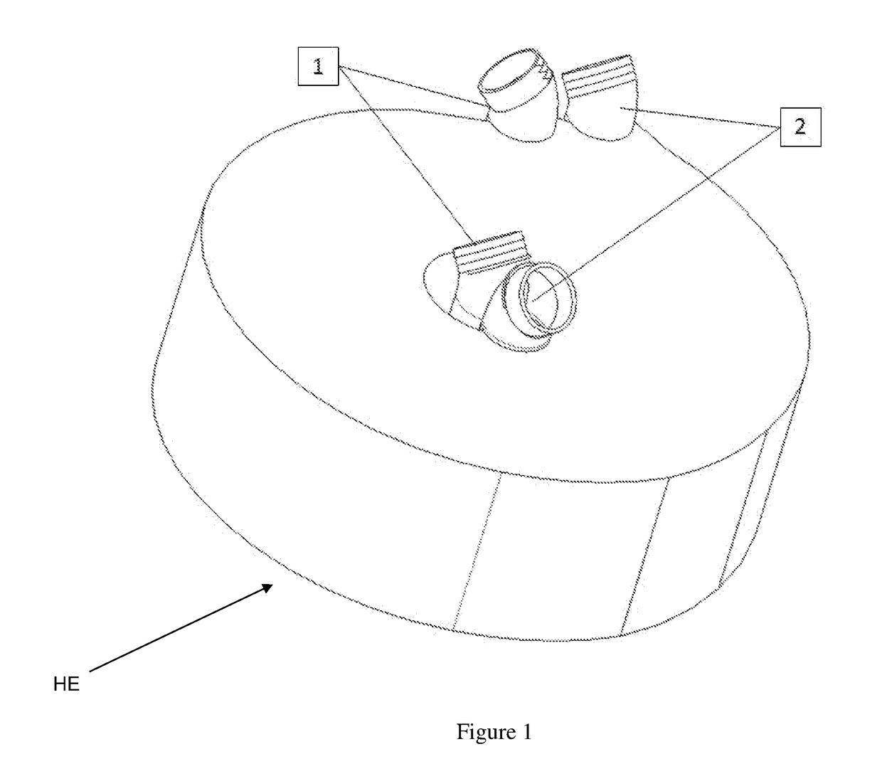
[0045]FIGS. 1-12 show two new and unique methods / techniques to route fluids to heat exchanger paths, as follows:

FIGS. 1-6

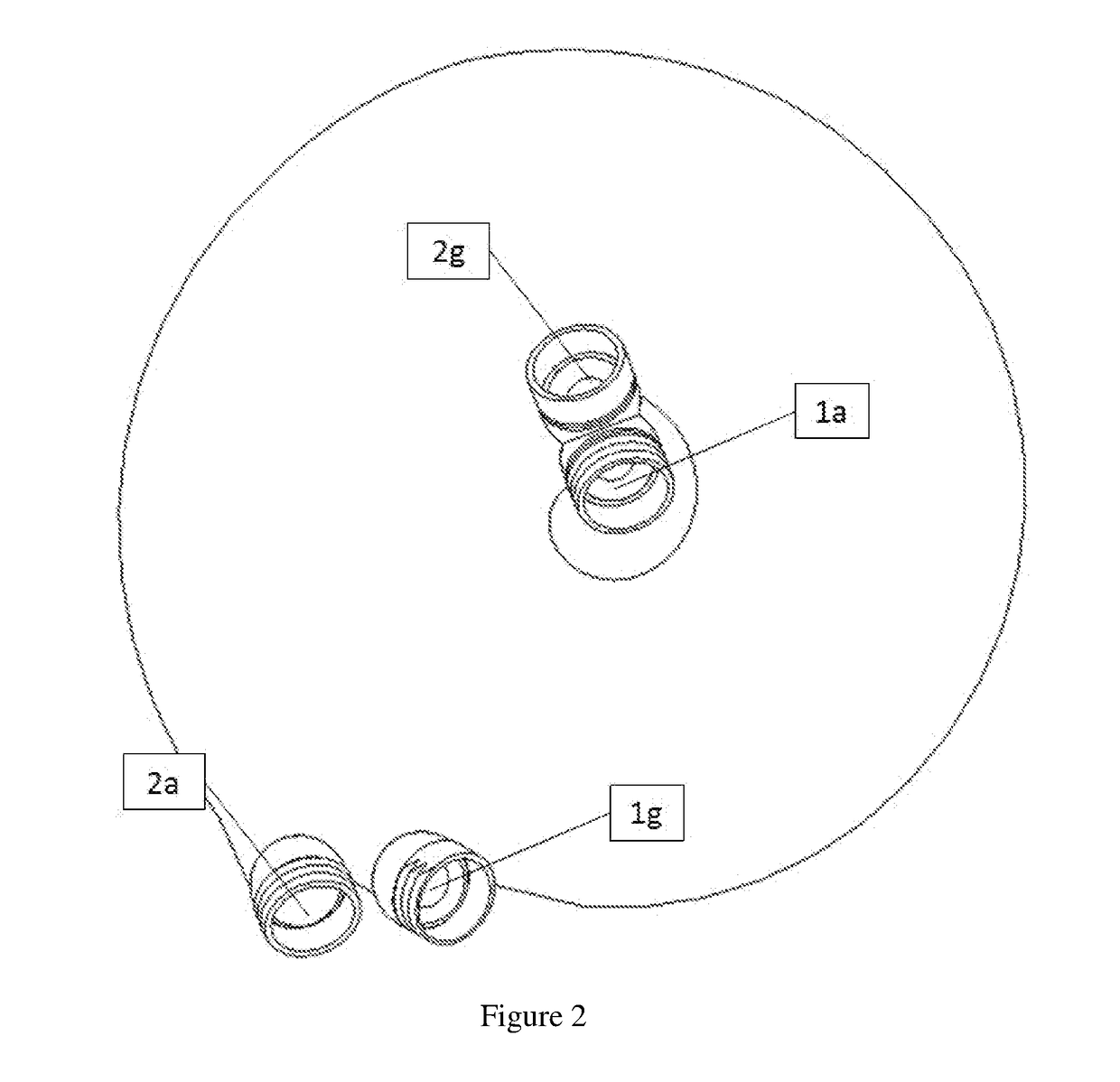
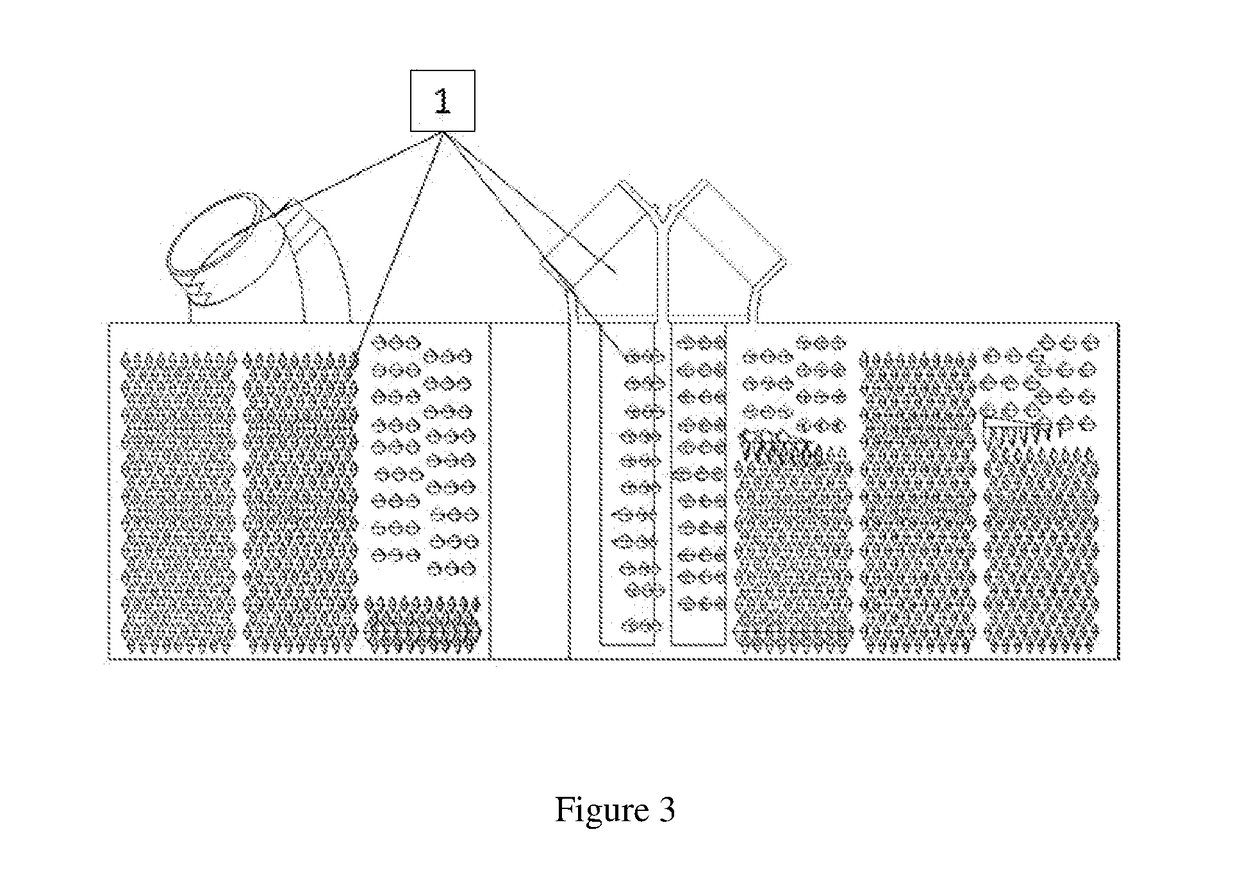
[0046]FIGS. 1-6 show a first method / technique that has the following components for each fluid path (1) and (2): A cold / hot fluid inlet (1a, 2a), a cold / hot inner / inlet route path (1b, 2b), a cold / hot inner / inlet manifold (1c, 2c), a cold / hot spiral fluid pathway (1d, 2d), a cold / hot outer / outlet manifold (1e, 2e), a cold / hot outer / outlet route path (1f, 2f), and a cold / hot fluid outlet (1g, 2g).

[0047]The function of this device will be described, e.g., by assuming that a hot fluid and cold fluid are being routed through the heat exchanger (HE) in a counterflow arrangement with the cold fluid being routed from the inside of the device towards the outside of the device in the cold fluid path generally indicated as (1), e.g., as shown in FIGS. 1 and 3, and the hot fluid being routed from the outside towards the inside in the hot fluid path generally indicated as (2)...


PUM


Abstract

A spiral heat exchanger features: a cold fluid inlet manifold, a hot fluid inlet manifold and at least one spiral fluid pathway. The cold fluid inlet manifold receives cold fluid and provide cold inlet manifold fluid. The hot fluid inlet manifold receives hot fluid and provide hot inlet manifold fluid. The at least one spiral fluid pathway includes cold spiral pathways configured to receive the cold inlet manifold fluid and provide cold spiral fluid pathway fluid, and hot spiral pathways configured to receive the hot inlet manifold fluid and provide hot spiral fluid pathway fluid. The cold spiral pathways and the hot spiral pathways are configured in relation to one another to exchange heat between the cold spiral pathway fluid and the hot spiral pathway fluid so that the hot spiral fluid pathway fluid warms the cold spiral fluid pathway fluid, and vice versa.

Description

CROSS-REFERENCE TO RELATED APPLICATIONS[0001]This application claims benefit to provisional patent application Ser. No. 62 / 538,214 (911-026.002-1 (F-STD-X0002US01)), filed 28 Jul. 2017; which is incorporated by reference in its entirety.[0002]This application is also related to U.S. patent application Ser. No. 15 / 618,466 (911-026.001-1 (F-STD-X0001US01)), filed 9 Jun. 2017, claiming benefit to provisional patent application Ser. No. 62 / 347,813, filed 9 Jun. 2016, which disclose 3D spiral heat exchangers and are both incorporated by reference in their entirety.[0003]This application is also related to U.S. patent application Ser. No. 15 / 966,706 (911-019.035-2 (F-B&G-X0034US01)), filed 30 Apr. 2018, claiming benefit to provisional patent application Ser. No. 62 / 491,325, filed 28 Apr. 2017, which disclose another work by the instant inventor related to using additive manufacturing, and are both incorporated by reference in their entirety.BACKGROUND OF THE INVENTION1. Field of Invention...

Claims


Application Information

Patent Timeline
Patent Type & Authority Applications(United States)
IPC IPC(8): F28D7/00F28F7/02
CPCF28D7/0033F28F7/02F28D7/0016F28D7/022F28D7/04F28F2255/18B33Y80/00
Inventor LOPES, JEFFREY D.
Owner FLUID HANDLING
Why Eureka
Try Eureka