Al technical title is built by PatSnap Al team. It summarizes the technical point description of the patent document.
a technology of shock awareness and shock awareness, applied in the field of shock awareness system, can solve the problems of swimmers being electrocuted, non-swimmers being electrocuted, swimmers being unable to detect shock,
Active Publication Date: 2019-04-11
SHOCK ALERT LLC
View PDF8 Cites 5 Cited by
Summary
Abstract
Description
Claims
Application Information
AI Technical Summary
This helps you quickly interpret patents by identifying the three key elements:
Problems solved by technology
Method used
Benefits of technology
Problems solved by technology
It is known that if a swimmer encounters a body of water with an electric field the swimmer can be electrocuted.
If the voltage differential is sufficiently high the current flowing through the swimmer's body can electrocute the swimmer or paralyze the swimmer causing the swimmer to drown.
In still other cases a nonswimmer may be electrocuted if he or she comes into incidental contact with a body of water, which has electrical leakage from an electrical source.
One of the difficulties is that oftentimes the source of leakage into the body of water may be sporadic or intermittent.
Method used
Image
Click on the blue label to locate the original text in one second.
Reading with bidirectional positioning of images and text.
Examples
Embodiment Construction
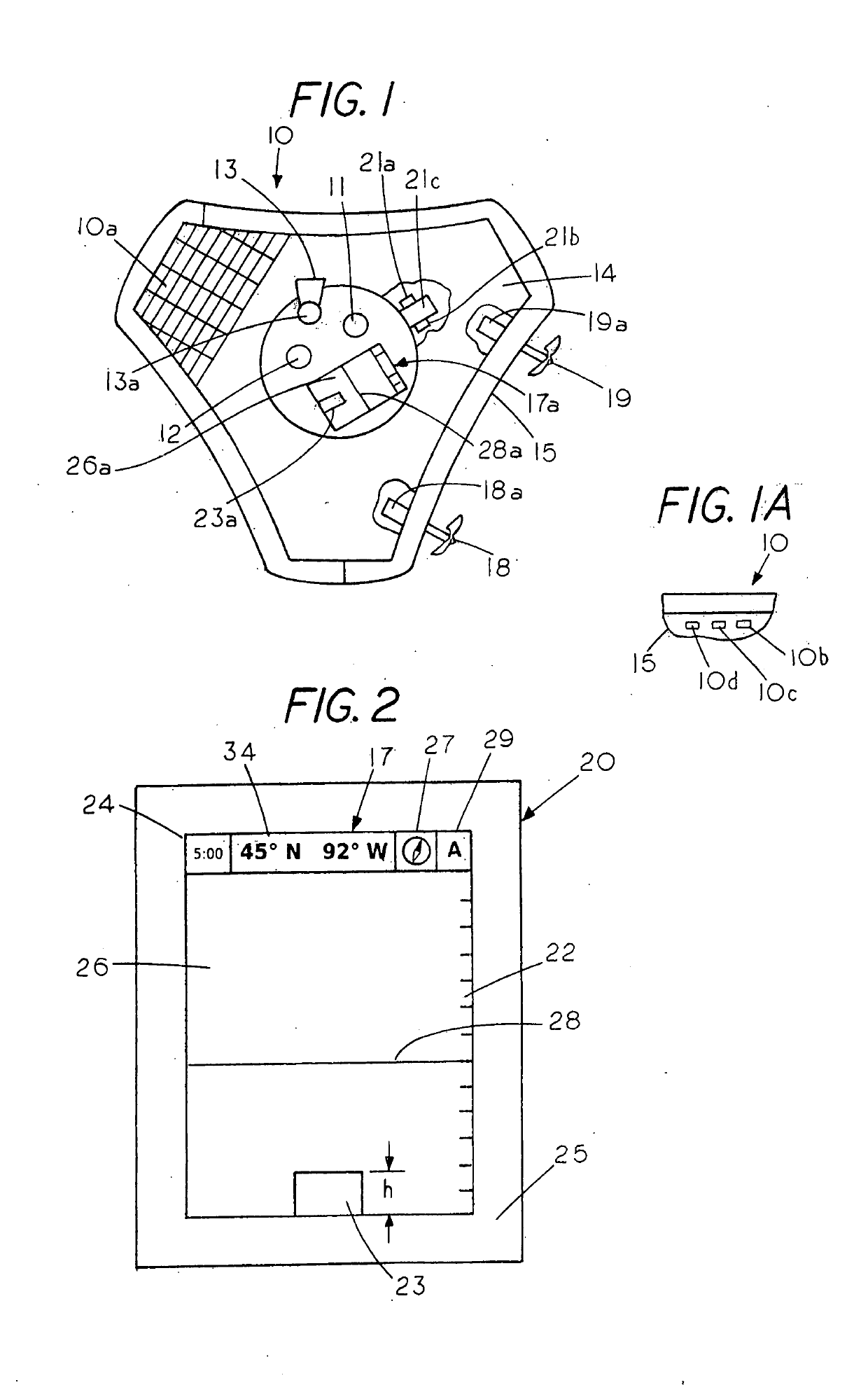
[0017]FIG. 1 is a top view partial cutaway view revealing components within a mobile floating shock detector 10, which forms a first part of a shock awareness system. The shock detector 10 having electrodes 10b, 10c and 10d (FIG. 1A), which are normally located on the housing 10 and below a water line of the shock detector 10. The electrodes contactable with the body of water proximate the buoyant housing 15 to measure electrical conditions such as voltage or current or both in the body of water.
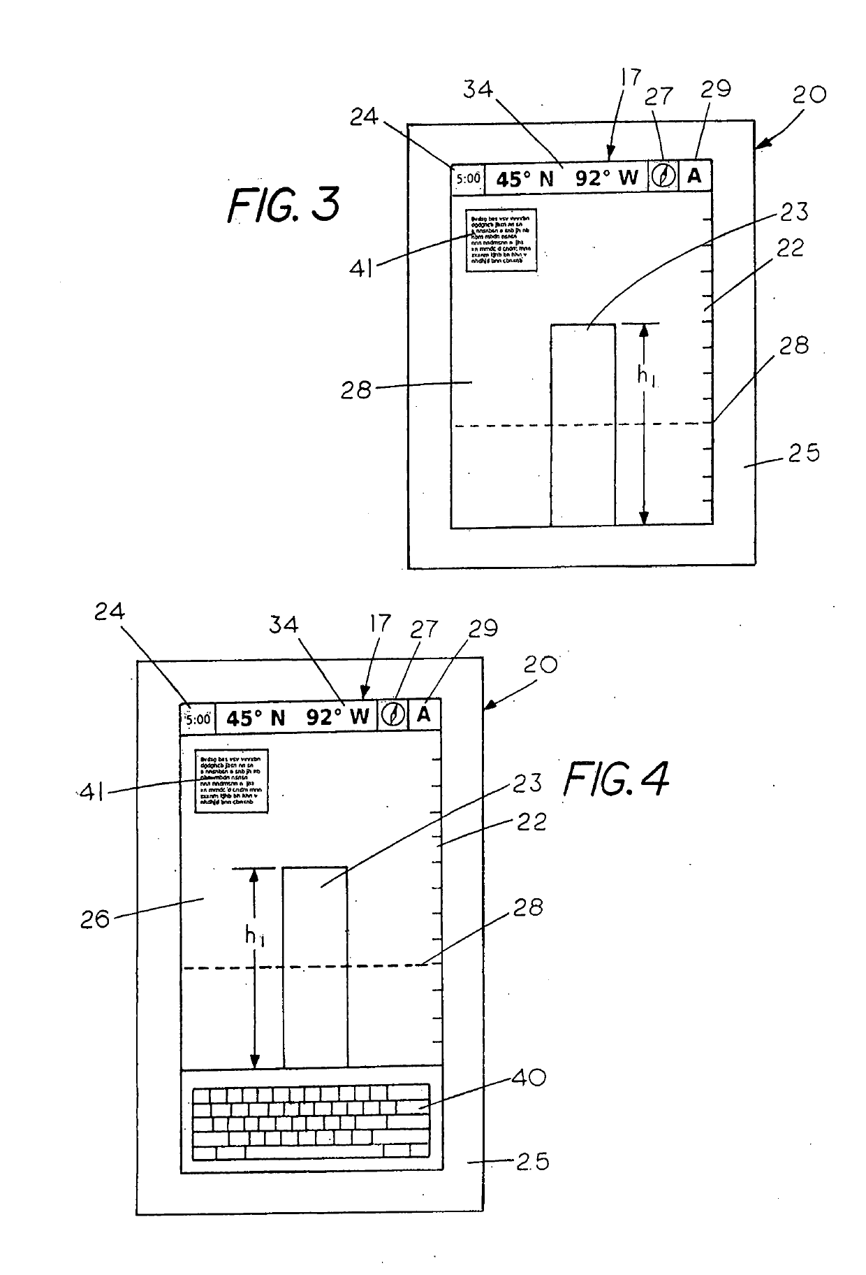
[0018]FIG. 2 shows a remote station 20 that forms a further part of the shock awareness system. The shock detector 10, which is wirelessly coupled to the remote station 20, forms part of the shock awareness system. In this example the shock detector 10 includes a visual display screen 26a and the remote station 20, which also includes a viewing or visual display screen 26 located within a bezel 25. Shock detector 10 also includes, a propulsion system, which includes a first propeller 18 powe...
PUM
Abstract
A shock awareness system including a shock detector for measuring an electrical condtion in a body of water and a remote station in communication with the shock detector with the shock awareness system displaying a measured electrical condtion in the body of water in relation to a known hazardous electrical condtion in the body of water to enable an operator to determine a level of danger in a body of water.
Description
CROSS REFERENCE TO RELATED APPLICATIONS[0001]This application is a continuation in part of U.S. Ser. No. 14 / 999,165 filed Apr. 5, 2016, which is a continuation in part of U.S. Ser. No. 14 / 998,497 filed Jan. 12, 2016 (now U.S. Pat. No. 9,678,119) which is a continuation of U.S. Ser. No. 13 / 987,731 filed Aug. 26, 2013 (now U.S. Pat. No. 9,285,396), which claims benefit of provisional application 61 / 743,134 filed Aug. 28, 2012 and a continuation in part of U.S. Ser. No. 15 / 330,129 filed Aug. 11, 2016 which is a continuation in part of U.S. Ser. No. 15 / 165,371 filed May 26, 2016, which is a continuation of U.S. Ser. No, 13 / 987.731 filed Aug. 26, 2013 (Now U.S. Pat. No. 9,285,396) which claims benefit of provisional application 61 / 743,184 filed Aug. 28, 2012.STATEMENT REGARDING FEDERALLY SPONSORED RESEARCH OR DEVELOPMENT[0002]NoneREFERENCE TO A MICROFICHE APPENDIX[0003]NoneBACKGROUND OF THE INVENTION[0004]It is known that if a swimmer encounters a body of water with an electric field the...
Claims
Application Information
Patent Timeline
Application Date:The date an application was filed.
Publication Date:The date a patent or application was officially published.
First Publication Date:The earliest publication date of a patent with the same application number.
Issue Date:Publication date of the patent grant document.
PCT Entry Date:The Entry date of PCT National Phase.
Estimated Expiry Date:The statutory expiry date of a patent right according to the Patent Law, and it is the longest term of protection that the patent right can achieve without the termination of the patent right due to other reasons(Term extension factor has been taken into account ).
Invalid Date:Actual expiry date is based on effective date or publication date of legal transaction data of invalid patent.
Patent Type & Authority Applications(United States)