Pump dispenser and containers

a technology of pump dispenser and container, which is applied in the direction of spraying apparatus, packaging, single-unit apparatus, etc., can solve the problem of product leakage into the packaging

Inactive Publication Date: 2019-04-25
RIEKE PACKAGING SYST LTD
View PDF0 Cites 5 Cited by
  • Summary
  • Abstract
  • Description
  • Claims
  • Application Information

AI Technical Summary

Benefits of technology

[0040]It is advantageous to cover the catch formations beneath the plunger head.

Problems solved by technology

Under repeated shock, vibration and inversion the lock-down threads sometimes work loose so that the plunger rises slightly and product leaks into the packaging.

Method used


Image

  • Pump dispenser and containers
  • Pump dispenser and containers
  • Pump dispenser and containers

Examples


Embodiment Construction

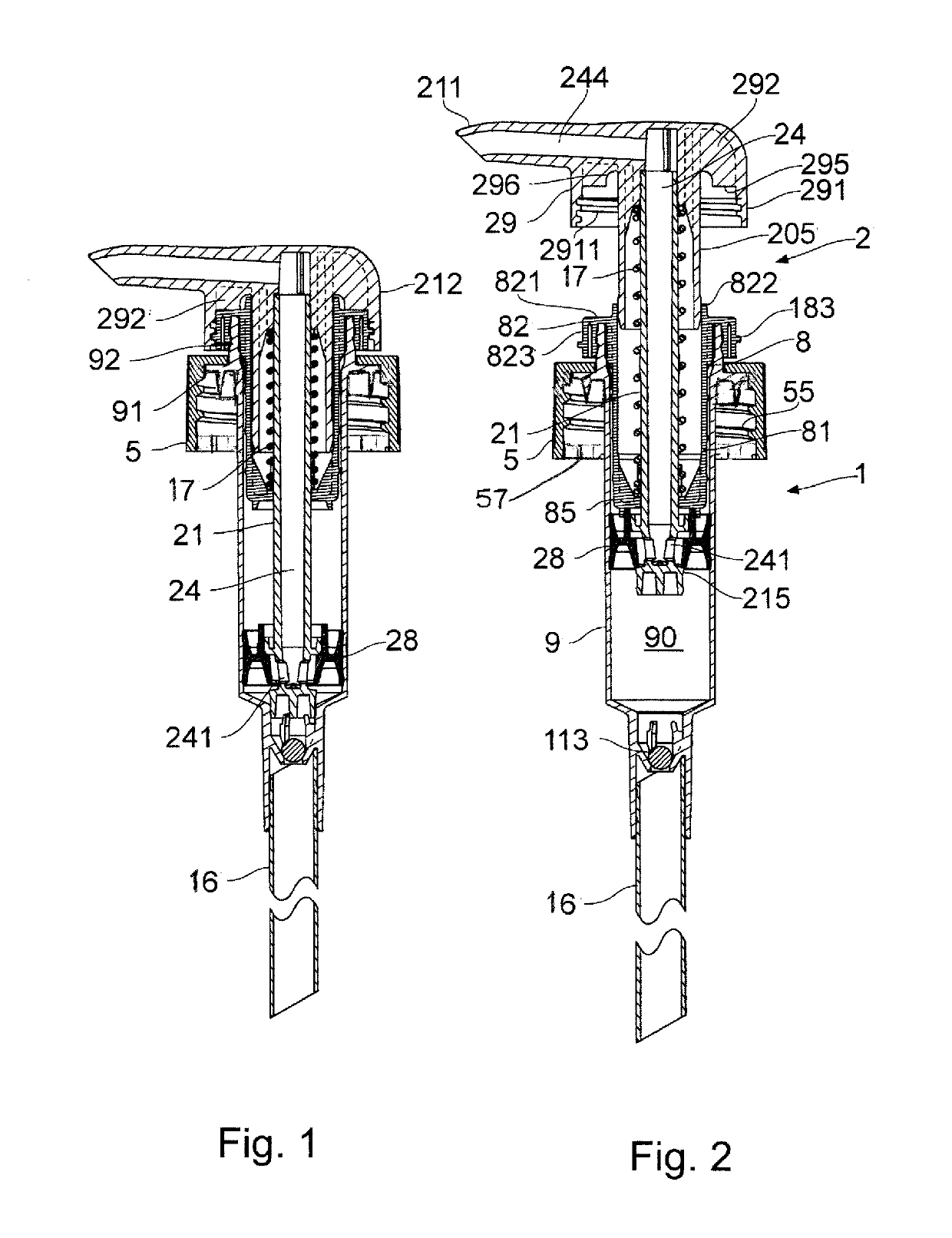
[0053]Firstly, general features of a pump are described.

[0054]FIGS. 1 and 2 show a moveable-nozzle pump with lock-down capability: a type of pump with which the present proposals are implemented.

[0055]The pump has a body 1 and a plunger 2. A closure cap 5 with internal threads 55 is for mounting the pump on the neck of a container.

[0056]The body 1 comprises a cylinder component 9 and a body insert component 8. The cylinder component 9 has a top annular rim 92 projecting up through a hole in the cap 5 and a radial flange 91 engaged beneath the cap, so that the cap 5 clamps the flange 91 down against the top of the container neck in use. The main lower part of the cylinder component 9 projects down axially into the container interior, converging at its bottom end to define an inlet valve seat for an inlet valve 113 e.g. a ball valve, and a socket for a dip tube 16.

[0057]The body insert component 8 is also generally cylindrical in form and comprises an inner tubular part 81 and a top c...


PUM


Abstract

A pump dispenser comprising a container having a neck (6) to which the pump is attached. A pump body (1) has an outward flange (91) through which it is supported on the edge of the container neck (6). A body/neck rotation stop mechanism (64,7) is provided by an interlock engagement between the pump body and the container neck, and has widely-spaced interlock projections (64) on the container neck (6), e.g. one or two projections, each having a circumferentially-directed abutment face (642). A series of spaced interlock teeth (71) projects down from the outward flange (91) of the pump body and these have respective abutment faces (711) to engage the neck projections and limit relative rotation of the pump body and neck. This can assure reliable action of a plunger-locking mechanism of the dispenser.

Description

FIELD OF THE INVENTION[0001]This invention has to do with pump dispensers of the type comprising a container for fluid product to be dispensed and a pump mounted in the neck of a container, usually by a discrete closure cap. Typically the pump has a plunger which operates in a pump body for pumping the product. Other aspects herein relate to containers with necks adapted for rotational locking to a component mounted thereon.BACKGROUND[0002]Typically the pump of a pump dispenser comprises a pump body defining a pump cylinder. The container is usually a plastic bottle, and has a neck with retaining formations e.g. a screw thread, snap ring, bead or groove. The pump body is usually mounted on the neck by a closure cap, usually a separate component, and typically with an outward flange of the pump body bearing down on the edge of the container neck. The closure cap fixes down onto the neck. The pump body extends down through the container neck into the container interior.[0003]The pump ...

Claims


Application Information

Patent Timeline
Patent Type & Authority Applications(United States)
IPC IPC(8): B05B11/00
CPCB05B11/306B05B11/3047B05B11/3067B05B11/3074B65D1/0246B05B11/1001B05B11/106B05B11/1067B05B11/1047B05B11/1074
Inventor KNIGHT, SIMON CHRISTOPHER
Owner RIEKE PACKAGING SYST LTD
Why Eureka
Try Eureka