Pneumatic tire
- Summary
- Abstract
- Description
- Claims
- Application Information
AI Technical Summary
Benefits of technology
Problems solved by technology
Method used
Image

Examples
first embodiment
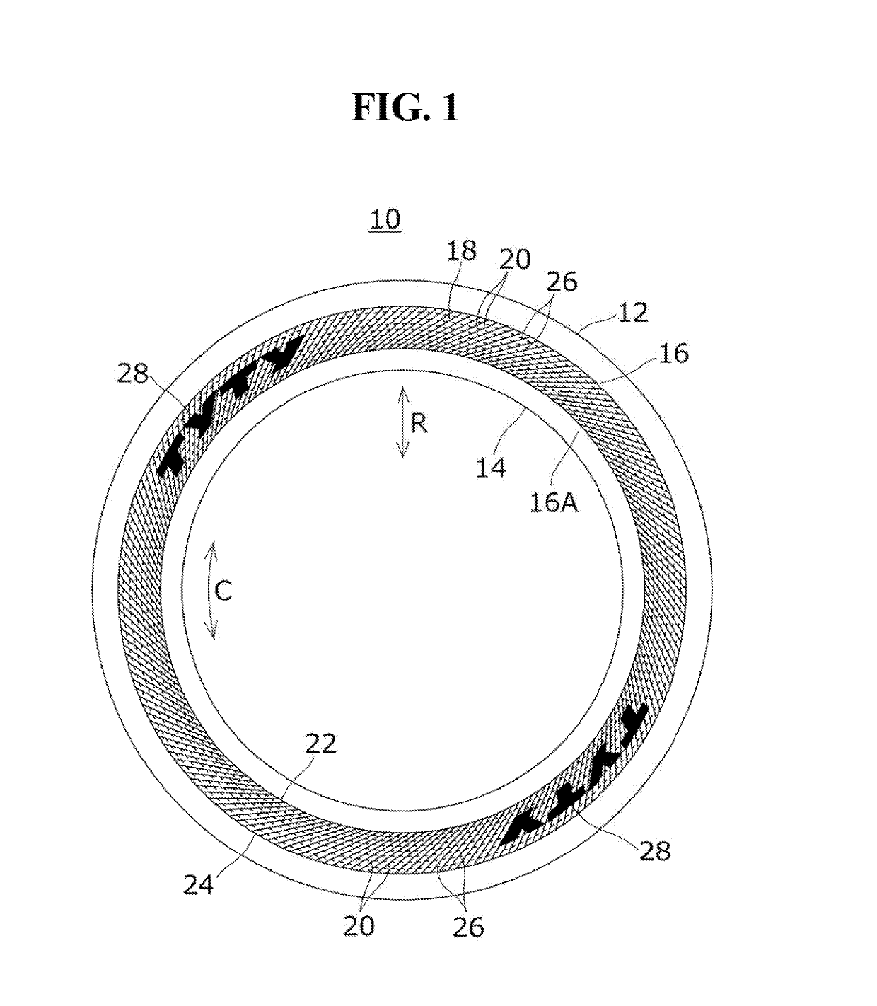
[0021]FIG. 1 is a view showing a side surface of a pneumatic tire 10 according to one embodiment. The pneumatic tire 10 includes a tread portion 12 forming a ground-contact surface, a pair of left and right bead portions 14, and a pair of left and right sidewall portions 16 interposed between the tread portion 12 and the bead portions 14. A serration portion 18 is provided to a surface (that is, outer surface) of at least one sidewall portion 16. The sidewall portions 16 are made of sidewall rubber 16A and the serration portion 18 is provided to a surface of the sidewall rubber 16A by vulcanization molding.
[0022]In an example described herein, the serration portion 18 is formed in an annular shape extending along a fill circumference in a tire circumferential direction C at a center of the sidewall portion 16 including a tire maximal width position. However, the serration portion 18 may be provided in a part in the tire circumferential direction C. For example, although illustration...
second embodiment
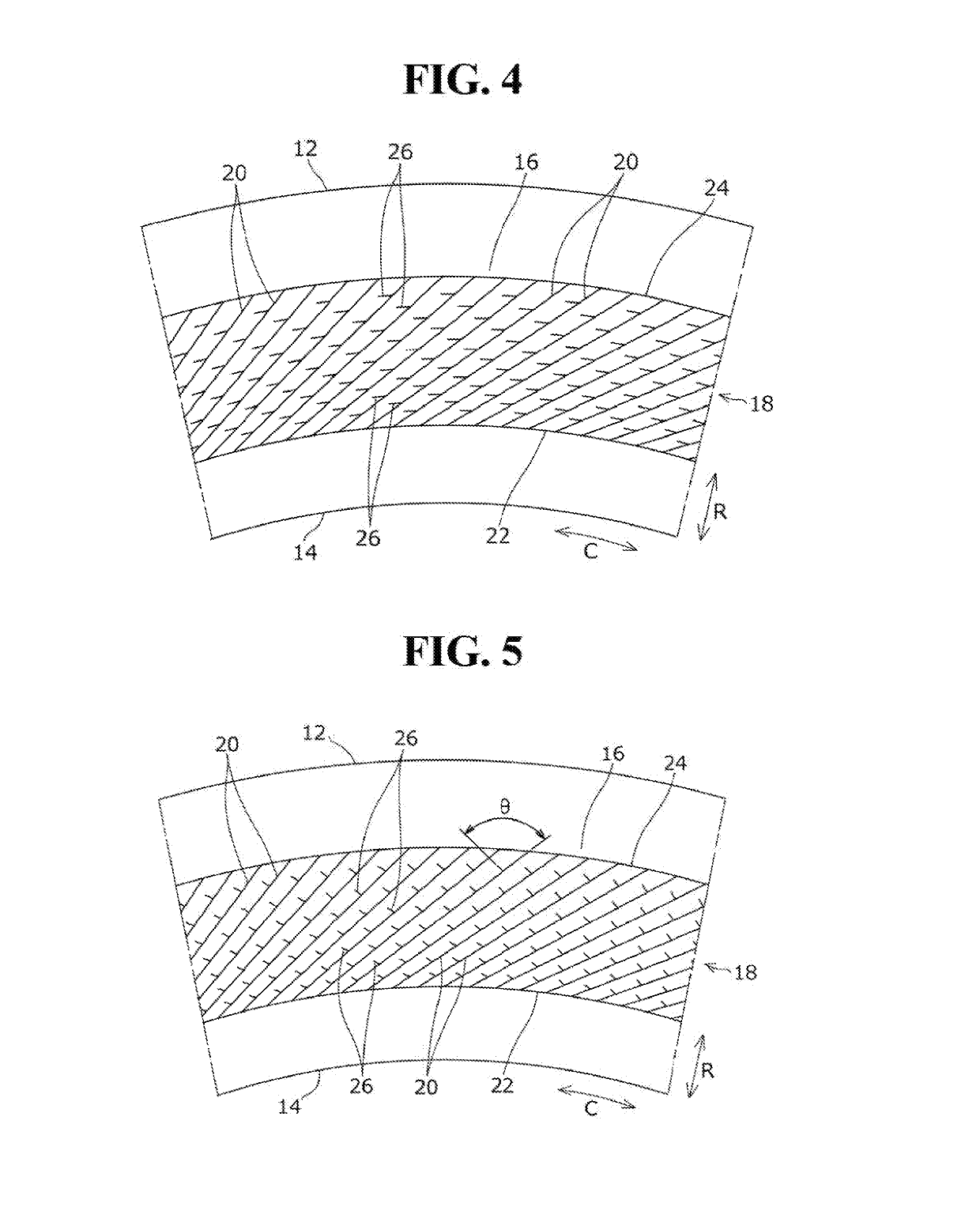
[0036]As is shown in FIG. 4, a serration portion 18 of a pneumatic tire according to a second embodiment is different from the first embodiment above in that sub-ridges 26 are disposed at different positions in a tire radial direction R between basic ridges 20 and 20 neighboring each other.
[0037]That is, the multiple sub-ridges 26 for each basic ridge 20 are disposed at same positions in the tire radial direction R between the basic ridges 20 and 20 neighboring each other in the first embodiment above. By contrast, the multiple sub-ridges 26 are disposed at different positions between the basic ridges 20 and 20 neighboring each other in the second embodiment. More specifically, as is shown in FIG. 4, the sub-ridges 26 are provided alternately in the tire radial direction R between the basic ridges 20 and 20 neighboring each other. Hence, the sub-ridges 26 are provided at every other basic ridge 20 in the tire circumferential direction C at each position in the tire radial direction ...
third embodiment
[0039]As is shown in FIG. 5, a serration portion 18 of a pneumatic tire according to a third embodiment is different from the first embodiment above in that sub-ridges 26 are provided substantially perpendicularly to bask ridges 20.
[0040]That is, the sub-ridges 26 do not extend along a tire circumferential direction C in the third embodiment. Instead, the sub-ridges 26 are provided to cross the basic ridges 20, which are inclined as described above, at a substantially perpendicular angle θ. The term, “substantially perpendicular”, referred to herein means an angle visually perceived substantially as being perpendicular, and for example, 90 degrees±10 degrees (that is, 80° to 100°).
[0041]In the third embodiment, the sub-ridges 26 are provided substantially perpendicularly to the basic ridges 20. Hence, longitudinal stiffness can be increased in comparison with the first embodiment above. The remaining configuration, a function, and an advantage of the third embodiment are same as the...
PUM
 Abstract
Description
Claims
Application Information
 - R&D Engineer
- R&D Manager
- IP Professional
- Industry Leading Data Capabilities
- Powerful AI technology
- Patent DNA Extraction
Browse by: Latest US Patents, China's latest patents, Technical Efficacy Thesaurus, Application Domain, Technology Topic.
© 2024 PatSnap. All rights reserved.Legal|Privacy policy|Modern Slavery Act Transparency Statement|Sitemap