Belt retractor for a vehicle safety belt

Active Publication Date: 2019-05-16
TRW AUTOMOTIVE GMBH
View PDF0 Cites 0 Cited by
  • Summary
  • Abstract
  • Description
  • Claims
  • Application Information

AI Technical Summary

Benefits of technology

[0021]According to one configuration, the pivoted lever is a leaf spring mad

Problems solved by technology

When the belt webbing is unwound from the belt reel at an increasing velocity, this leads to angular acceleration of the belt reel.
If the angular acceleration exceeds the trigge

Method used


Image

  • Belt retractor for a vehicle safety belt
  • Belt retractor for a vehicle safety belt
  • Belt retractor for a vehicle safety belt

Examples


Example

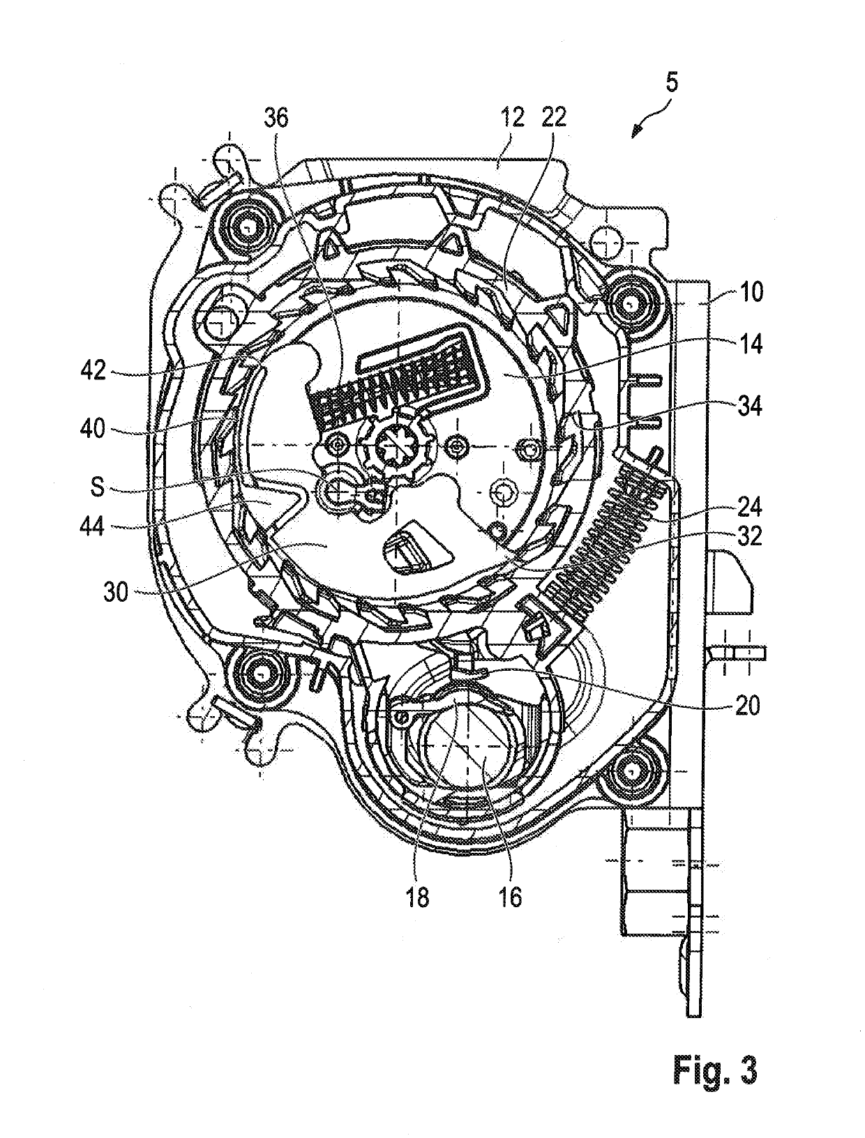
[0045]FIG. 3 illustrates a second embodiment of a belt retractor according to the invention. For the components known from the preceding embodiment the same reference numerals are used and the foregoing explanations are referred to in this respect.

[0046]The substantial difference between the first and second embodiments consists in the fact that a pivoted lever 40 which is connected to the inertia pawl 30 at one end 42, namely at the end facing away from the inertia pawl tip 32, is provided in the second embodiment. At the other end of the pivoted lever 40 a leverage mass 44 is provided.

[0047]The pivoted lever 40 along with the leverage mass 44 is formed integrally with the remaining inertia pawl 30 here. The inertia pawl may be injection-molded together with the pivoted lever 40 and the leverage mass 44, for example.

[0048]The pivoted lever 40 is configured in the form of a spring and, unless any external forces are acting, maintains the leverage mass 44 at the position shown in FIG...

Example

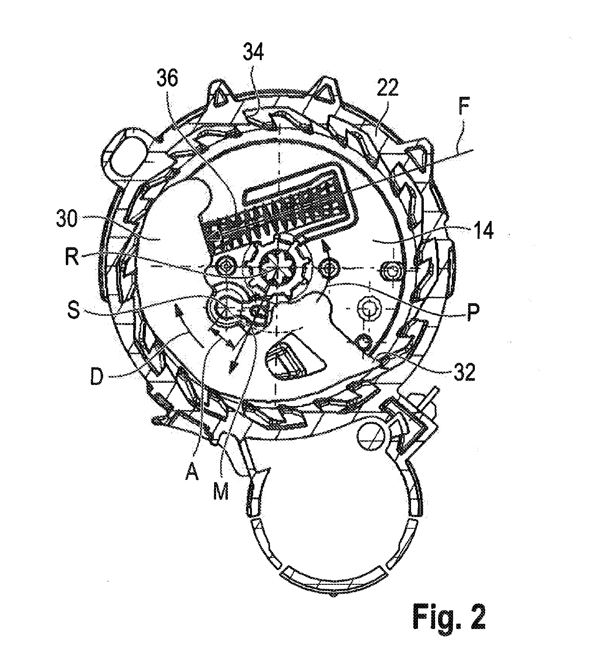
[0049]In the same way as in the first embodiment, also in the second embodiment the rotational speed of the belt reel 14 results in a centrifugal force which ultimately produces a torque counteracting the action of the return spring 36. Thus, the webbing-sensitive locking can be substantially triggered by exceeding an angular acceleration of the belt reel and substantially by exceeding a limit speed of the belt reel or by a mixture of the rotational speed of the belt reel and the angular acceleration of the belt reel.

[0050]FIG. 4 illustrates a variant of the second embodiment. The difference from the embodiment according to FIG. 3 consists in the fact that in the variant according to FIG. 4 the pivoted lever 40 is not formed integrally with the inertia pawl 30 but is in the form of a separate component. The pivoted lever 40 is especially in the form of a leaf spring which is suspended in the inertia pawl 30 at the end thereof facing away from the inertia pawl tip 32 and at the oppos...


PUM


Abstract

The invention relates to a belt retractor (5) for a vehicle seat belt system, comprising a frame (10), a belt reel (14) which is rotatably arranged within the frame (10), and a locking system which can lock the belt reel in a webbing-sensitive manner, wherein the locking system includes an inertia pawl (30) which per se co-rotates with the belt reel (14) and is pivotable from a home position in which the belt reel is freely rotatable about a pivot axis (S) to a locking position, characterized in that a means to trigger pivoting of the inertia pawl (30) is provided which is responsive to exceeding a predetermined centrifugal force.

Description

RELATED APPLICATIONS[0001]This application corresponds to PCT / EP2017 / 063078, filed May 31, 2017, which claims the benefit of German Application No. 10 2016 006 750.0, filed Jun. 6, 2016, the subject matter of which are incorporated herein by reference in their entirety.BACKGROUND OF THE INVENTION[0002]The invention relates to a belt retractor for a vehicle seat belt system comprising a frame, a belt reel which is rotatably disposed in the frame and a locking system which can lock the belt reel in a webbing-sensitive manner, wherein the locking system has an inertia pawl which per se co-rotates with the belt reel and is pivotable from a home position in which the belt reel is freely rotatable about a pivot axis to a locking position.[0003]A seat belt for a vehicle occupant to belt up is received on the belt reel. In the normal condition, the belt reel is freely rotatable against the action of a return spring in a webbing extension direction. Thus, the vehicle occupant may extend the ...

Claims


Application Information

Patent Timeline
IPC IPC(8): B60R22/38
CPCB60R22/38B60R22/405
Inventor HIRSCH, JOHANNRINK, JURGENLITTAU, FRIEDRICH
Owner TRW AUTOMOTIVE GMBH
Why Eureka
Try Eureka