
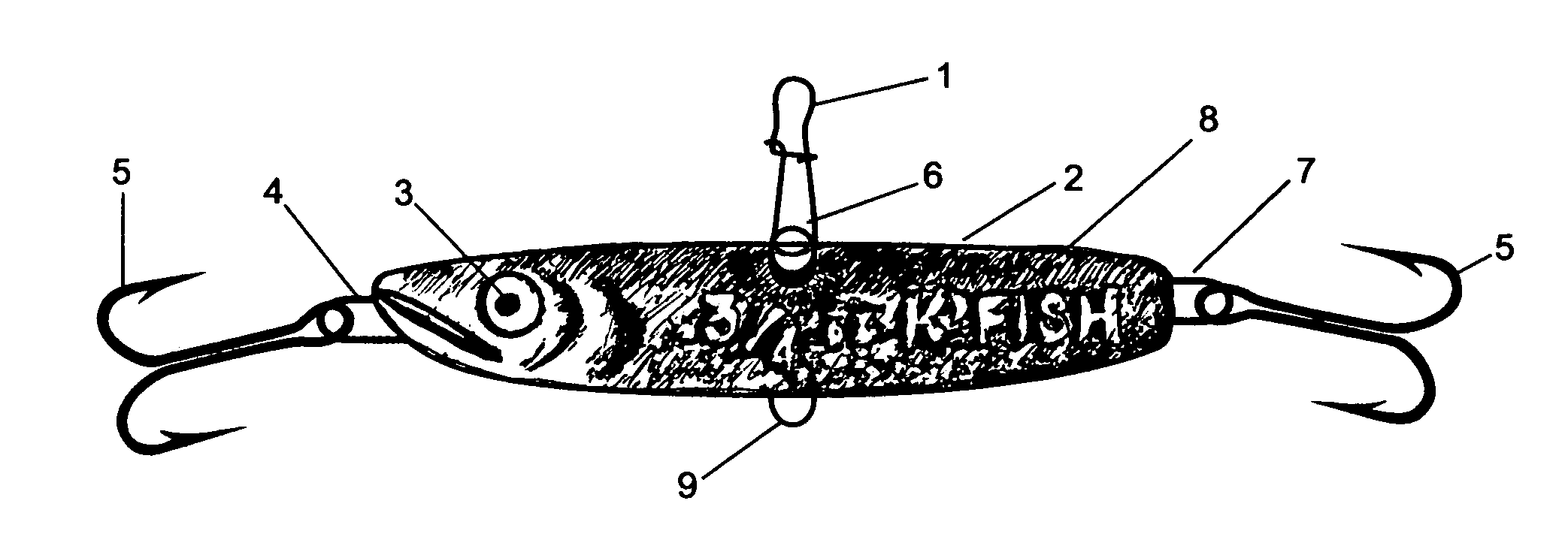
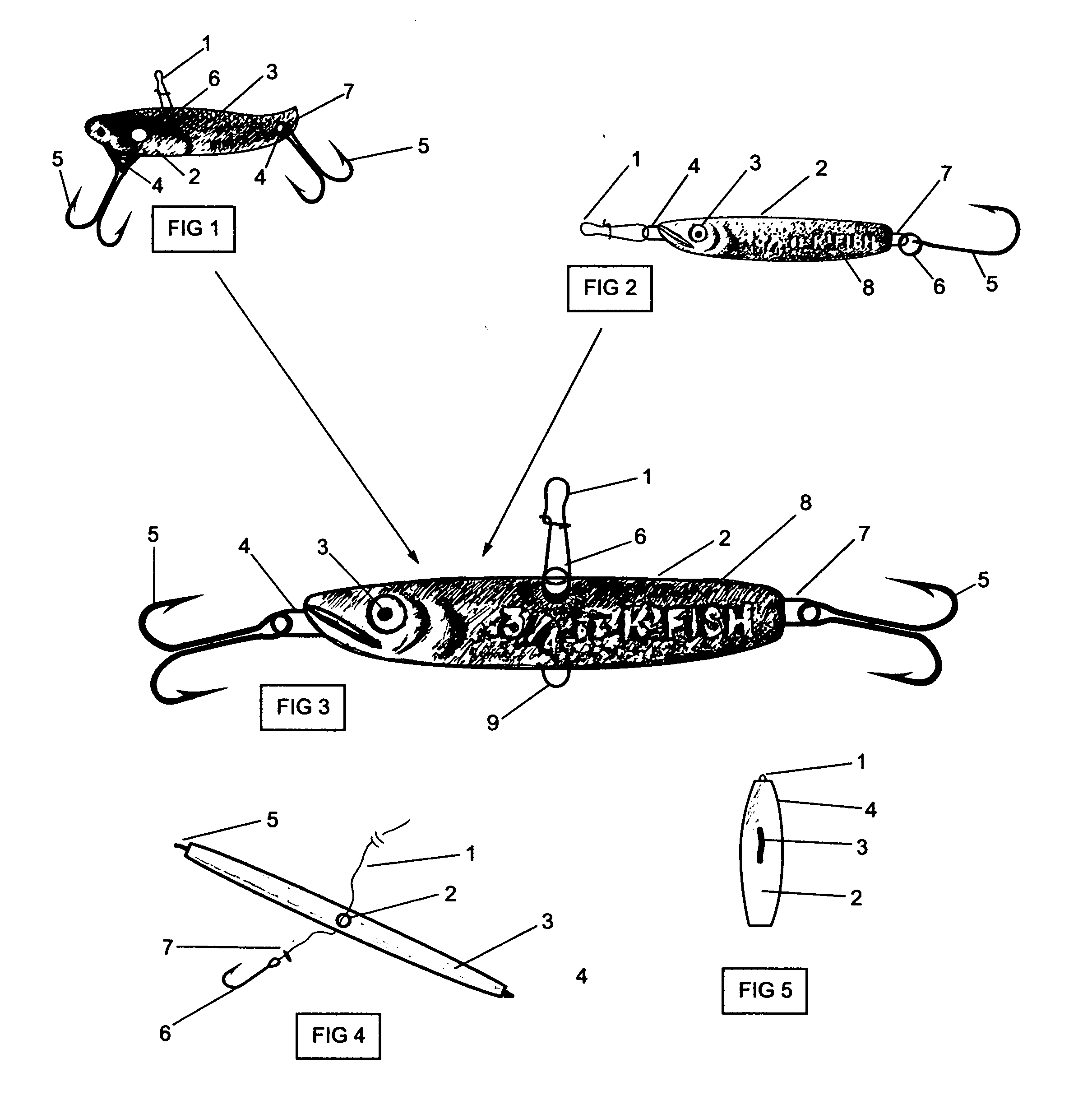
Two in one, vibrating metal jig fishing lure (a.k.a. "Sonic Kandlefish").

a metal jig and lure technology, applied in fishing, fish-hooks, animal husbandry, etc., can solve the problems of maximum hydrosonic vibration and exceed the effect of all other lure types available, and achieve the effect of maximizing the hydrosonic vibration and action

Inactive Publication Date: 2012-11-15
ROSKO PETER JOHN
View PDF43 Cites 2 Cited by
  • Summary
  • Abstract
  • Description
  • Claims
  • Application Information

AI Technical Summary

Benefits of technology

[0028]Historically, all metal jigs are attached to a fishing line at their nose. By adding an innovative second attachment to the dorsal balance point on a metal jig (the invention), this most versatile lure type is further-enhanced in its ability to maximize its hydrosonic vibration, and action, while vertical jigging.

Problems solved by technology

Furthermore, the resultant vibration exceeds that of all other lure types available in the industry.
Line attachment to the dorsal insert results in maximum hydrosonic vibration primarily when vertical jigging.

Method used


Image

  • Two in one, vibrating metal jig fishing lure (a.k.a. "Sonic Kandlefish").
  • Two in one, vibrating metal jig fishing lure (a.k.a. "Sonic Kandlefish").

Examples


Embodiment Construction

[0074]The invention is the first true metal jig to incorporate a line attachment on the top of its back (dorsal), positioned at its balance point. It is a “2 in 1” hybrid lure with combined blade bait and metal jig actions. Dorsal and nose line attachments, on the same metal jig, requires precise balance for each type of action (blade bait and metal jig) to perform with consistent efficacy.

[0075]With the dorsal line attachment, the invention has unsurpassed high frequency hydrosonic vibration on both the lift and fall. On the lift, the action is exclusively a tight, side-to-side vibration similar to a reciprocal, fast-moving windshield wiper. On the fall, gravity initially causes the same side-to-side vibration then that movement transforms to the darting-gliding-fluttering action of a metal jig.

[0076]To change the hybrid action from the “Sonic Kandlefish” (dorsal) to the original metal jig “Kandlefish” (nose), simply remove the nose hook and reposition the line attachment from its ...


PUM


Abstract

All traditional metal jigs (aka “jigging spoons”) have their lines attached to a metal insert positioned in the nose portion. The invention is a first time radical industry departure by including two primary dynamic functional attachment points in a single metal jig. It is a “2 in 1” hybrid lure with combined blade bait and metal jig actions. The invention is easily converted to a multiplicity of lure actions simply by changing its line and hook attachments from the nose insert to the dorsal insert positioned at its critical balance point on the top of its back. The resultant unmatched hydrosonic vibration, versatility and life-like natural appearance enable the invention to be effectively fished in all fresh and salt waters, worldwide.

Description

CROSS REFERENCES TO RELATED APPLICATIONSField of Search:[0001]U.S. Class / Sub-Class: 42.33; 42.34; 42.45; 42.46; 42.48; 42.49; 42.51; 42.52; 43 / 42.32; 43 / 42.50; 43 / 42.51[0002]International Class: A01K 85 / 00 / 04 / 12 / 14References Cited:U.S. Patent Documents:[0003]U.S. Pat. No. 1,875,122 . . . 8 / 1932 Olson . . . 43 / 42.5[0004]U.S. Pat. No. 2,593,027 . . . 5 / 1949 Heino . . . 43 / 42.5[0005]U.S. Pat. No. 2,480,580 . . . 8 / 1949 Hopkins . . . 43 / 42.5[0006]U.S Pat. No. 2,484,747 . . . 10 / 1949 Russell . . . 43 / 42.5[0007]U.S. Pat. No. 2,511,002 . . . 6 / 1950 Perry . . . 43 / 42.5[0008]U.S. Pat. No. 2,632,277 . . . 3 / 1953 Cogswell . . . 43 / 42.49[0009]U.S. Pat. No. 2,657,495 . . . 11 / 1953 Eppinger . . . 43 / 42.5[0010]U.S. Pat. No. 2,809,462 . .. 5 / 1954 Wallis . . . 43 / 42.5[0011]U.S. Pat. No. 2,717,468 . . . 9 / 1955 Clough . . . 43 / 42.51[0012]U.S. Pat. No. 3,094,804 . . . 6 / 1963 Walton . . . 43 / 42.5[0013]U.S. Pat. No. 3,169,337 . . . 8 / 1963 McGregor . . . 43 / 42.5[0014]U.S. Pat. No. 3,497,986 . . . 3 / 1968 B...

Claims


Application Information

Patent Timeline
Patent Type & Authority Applications(United States)
IPC IPC(8): A01K85/01A01K83/00A01K85/00
CPCA01K85/16
Inventor ROSKO, PETER JOHN
Owner ROSKO PETER JOHN
Learn More