In situ process to recover heavy oil and bitumen

a technology of heavy oil and bitumen, applied in the field of in situ process to recover heavy oil and/or bitumen, can solve the problems of increasing the temperature of heavy oil or bitumen, affecting process economics, and unclear what the optimal amount of non-condensable gas is, and achieves the effect of maximizing the solubility of solven

Inactive Publication Date: 2008-01-24
PARAMOUNT RESOURCES LTD
View PDF16 Cites 81 Cited by
  • Summary
  • Abstract
  • Description
  • Claims
  • Application Information

AI Technical Summary

Benefits of technology

[0018] In one embodiment of the invention, a method is provided to extract heavy oil or bitumen from a reservoir located underground. The reservoir is penetrated by a horizontal wellpair that comprise a top injection well and a bottom production well both being substantially parallel to each other. In the method, steam, solvent, and non-condensable gas are injected through the injection well into the reservoir over time while reservoir fluids are produced through the production well. The injected fluids enter a vapor chamber that surrounds and extends above the injection well. In the present invention, the injection rates and injection pressure are controlled in order to minimize heat losses to the overburden and maximize the action of the solvent in reducing the viscosity of the heavy oil and / or bitumen. Additionally, the operating pressure is controlled together with the relative amounts of steam, solvent, and non-condensable gas to maximize the solvent recovery from the process. The partial pressure of the solvent is controlled in the vapor chamber as the process is evolved.
[0020] The recovery method may include the additional step of adjusting the injection pressure and relative amounts of steam, solvent, and non-condensable gas to control the vapor chamber temperature to enhance the solubility of solvents.
[0022] A further object of one embodiment of the present invention is to provide a method for recovering heavy hydrocarbons from an underground reservoir containing heavy hydrocarbons, an injection well and a production well, comprising injecting steam into the reservoir, to form a steam vapor chamber, co-injecting predetermined quantities of steam, hydrocarbon solvent and non-condensable gas into the steam vapor chamber to maximize the solubility of the solvent in the heavy hydrocarbons, recovering produced hydrocarbons through the production well, adjusting the volume of steam injected into the vapor chamber to be subordinate to the volume of hydrocarbon solvent and non-condensable gas whereby partial pressure of the steam in the chamber is reduced and hydrocarbon solvent solubility is elevated in the heavy hydrocarbons, and recovering further produced hydrocarbons through the production well.

Problems solved by technology

Typically, in situ methods are used in heavy oil or bitumen deposits that are greater than about 70 m deep where it is no longer economic to recover the hydrocarbon by current surface mining technologies.
The steam loses its latent heat to the cool heavy oil or bitumen at the edges of the steam chamber and as a result raises the temperature of the heavy oil or bitumen.
The major capital and operating costs of SAGD involve the facilities to generate steam and re-cycle produced water back to the steam generators.
At present, it remains unclear what the optimal amount of non-condensable gas that should be added to the injected steam.
There are two issues about this process: first the process uses high solvent to hydrocarbon ratio and second the solvents are typically more valuable than the produced hydrocarbon.
Both of these issues adversely impact process economics.
Also there are unresolved issues on how to prevent significant solvent losses to the reservoir which will be vitally important for economic success of the process.
Additionally, the operating pressure range of VAPEX is limited because of required condensation of the injected gaseous solvent at the edges of the vapor chamber.

Method used


Image

  • In situ process to recover heavy oil and bitumen
  • In situ process to recover heavy oil and bitumen
  • In situ process to recover heavy oil and bitumen

Examples


Embodiment Construction

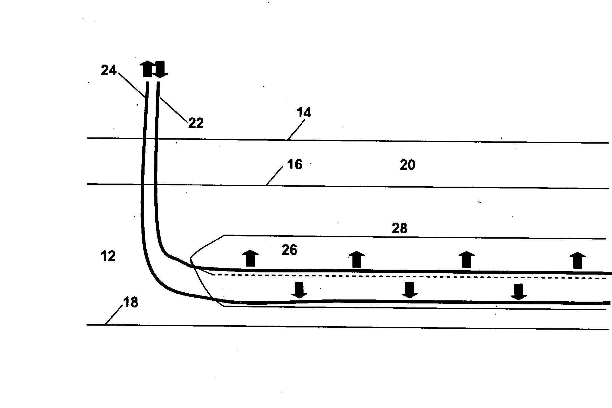
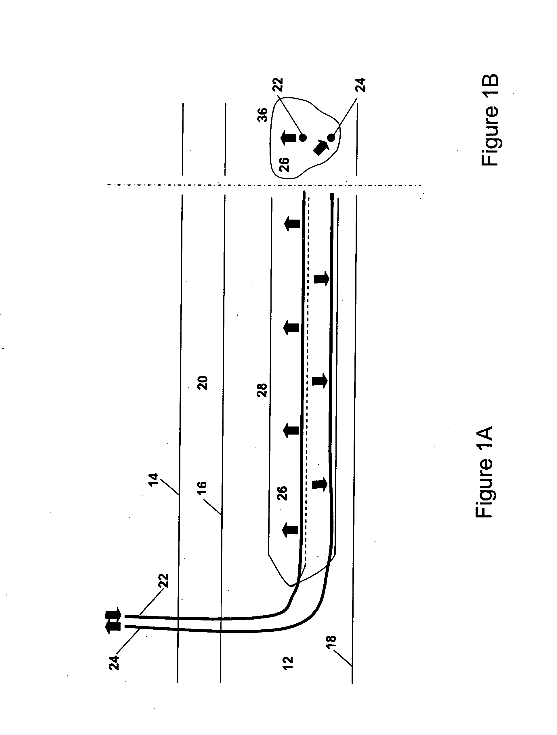
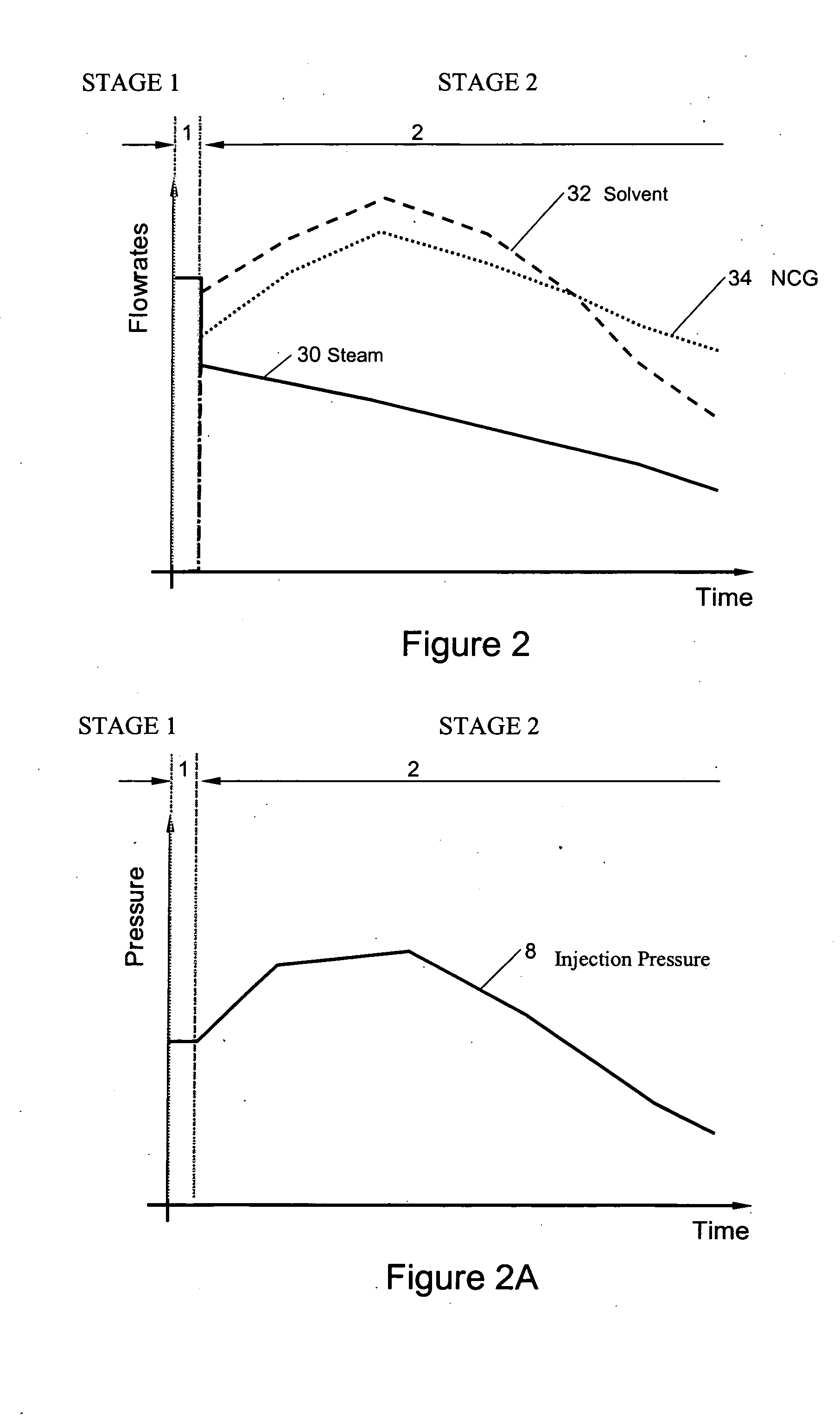
[0034] With reference to the Figures, a phased heating and solvent enhanced recovery process for recovery of in situ bitumen or heavy oil is described. Broadly, the invention consists of a sequence of fluid injection and operating pressure changes that results in significantly improved heavy oil or bitumen production from a heavy oil or bitumen reservoir.

[0035] Heavy oil and bitumen is a more viscous material compared to light oils at in situ initial reservoir temperatures and pressures. Also, at elevated temperatures, heavy oil and bitumen has higher viscosity than lighter hydrocarbons such as solvent at the same temperature. At even more elevated temperatures, even though heavy oil and bitumen remains in liquid state, the solvent can be in the gaseous state and freely move throughout the reservoir providing there is a driving pressure gradient to motivate the solvent motion. The amount of solvent that can dissolve in heavy oil or bitumen depends on the reservoir temperature and p...


PUM


Abstract

An in situ reservoir recovery process consisting of a horizontal injection well and a horizontal production well to extract bitumen or heavy oil from a reservoir. The process consists of a first phase operated at high-pressure in which steam, hydrocarbon solvent and non-condensable gases are injected into the reservoir and a second phase in which the injected fluids are transitioned to a high content of solvent and non-condensable gas and a reduced amount of steam to maintain a warm zone in the neighbourhood of the injection and production wells. The steam injection is sufficient to promote vapor transport of the solvent into the vapor depletion chamber and maintain the process at elevated temperatures in order to maintain low fluid viscosities in the production wellbore and to achieve preferred phase behaviour of the solvent hydrocarbon and the heavy oil or bitumen. The operating pressure of the process is controlled to prevent losses of the solvent hydrocarbon to the formation and to aid in solvent production to the production well in order for future re-cycling.

Description

FIELD OF THE INVENTION [0001] The present invention relates to a method to improve heavy oil and / or bitumen recovery from a hydrocarbon reservoir. The invention, in particular, relates to a process in which steam, solvent and non-condensable gas injection rates and pressure into an injection well are phased throughout the process to achieve improved thermal efficiency, mobilization of heavy oil and / or bitumen within the hydrocarbon reservoir and improved solvent recovery. BACKGROUND OF THE INVENTION [0002] There are many methods that are used to recover in situ heavy oil or bitumen from oilsands reservoirs. Typically, in situ methods are used in heavy oil or bitumen deposits that are greater than about 70 m deep where it is no longer economic to recover the hydrocarbon by current surface mining technologies. Depending on the operating conditions of the in situ process and the geology of the heavy oil or bitumen reservoir, in situ processes can recover between about 25 and 75% of the...

Claims


Application Information

Patent Timeline
Patent Type & Authority Applications(United States)
IPC IPC(8): E21B47/00E21B43/24E21B43/22
CPCE21B43/2406E21B43/16E21B43/2408
Inventor GATES, IAN DONALDBUNIO, GARY
Owner PARAMOUNT RESOURCES LTD
Why Eureka
Try Eureka