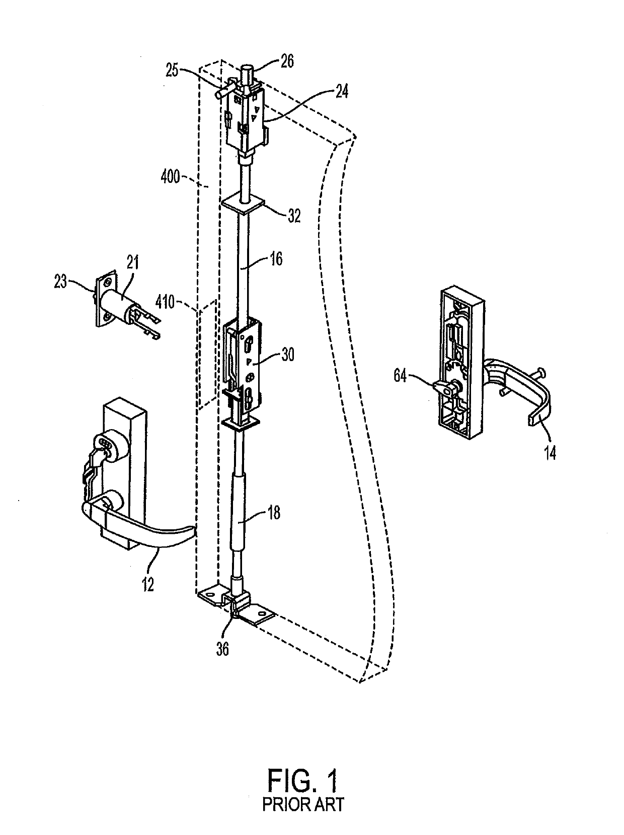
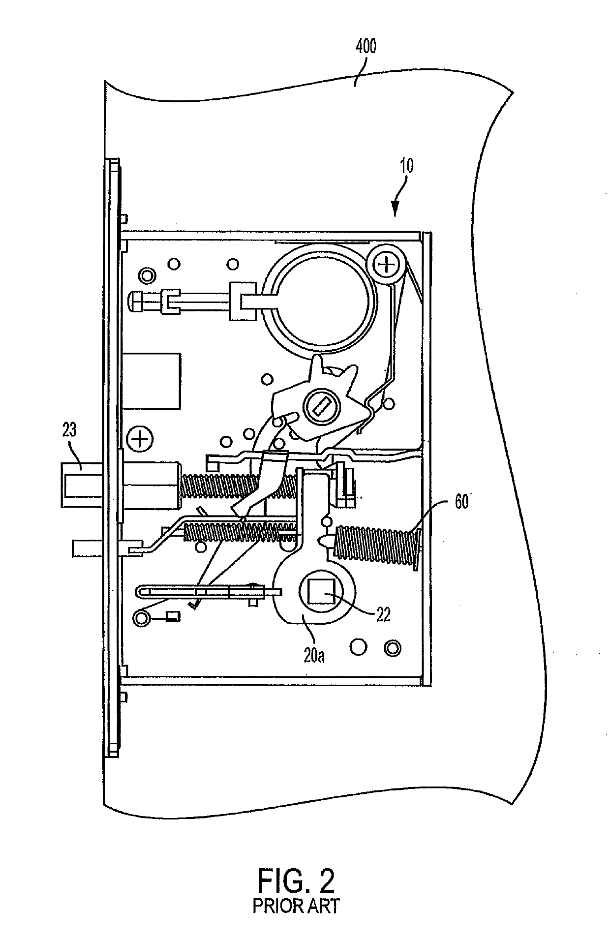
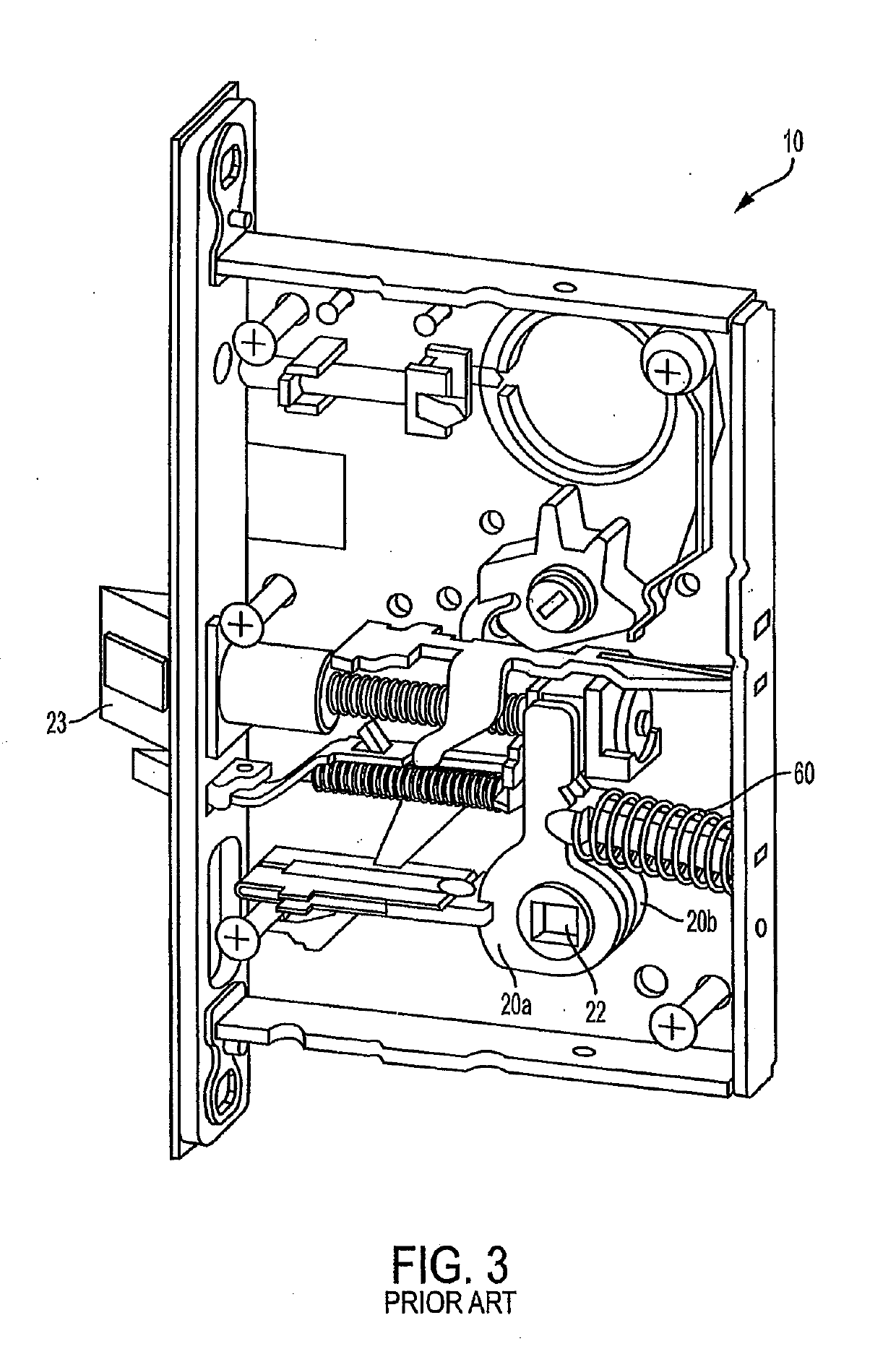
Mortise lock with multi-point latch system

a multi-point, latching technology, applied in the direction of latching locks, wing openers, building locks, etc., can solve the problems of inability to use a multi-point lock system, cumbersome method of latch extension/retraction, and difficulty for handicapped persons, so as to restrict the loosening of the button

Active Publication Date: 2019-06-20
SARGENT MANUFACTURING CO INC
View PDF0 Cites 0 Cited by
  • Summary
  • Abstract
  • Description
  • Claims
  • Application Information

AI Technical Summary

Benefits of technology

[0013]It is another object of the present invention to provide an apparatus and method that permits positive attachment and verification of retention of a vertical rod in a multi-point latching system.
[0054]The button may include a planar face and an outwardly stepped flat edge portion on a head of the button. A gate member is slideable in at least one opening in a housing in a direction parallel to the axis of reception of a member. The gate member includes an edge for contacting the button head flat edge, where the button planar face and the gate member come in contact when the gate member is in the closed position portion to restrict loosening of the button.

Problems solved by technology

There is currently no standard mortise lock that is able to actuate vertical rod door latches.
There is currently no multi-point lock system which allows for adjustment of latch projections while the door is hung, nor is there a mechanism for ensuring that latch projection adjustments for the top and / or bottom vertical rod latch(es) are from center.
This method of latch extension / retraction can be cumbersome and difficult for handicapped persons.
With the vertical rod and latch assembly typically concealed inside a cavity in the door, installation of the rods is complicated due to the inability of the installer to have a clean line of sight to the connection between the lock interface and the rod.

Method used


Image

  • Mortise lock with multi-point latch system
  • Mortise lock with multi-point latch system
  • Mortise lock with multi-point latch system

Examples


embodiment 140

[0157]The set screw 140 or 140′ has threads and is received in a comparably threaded opening in the housing oriented in a direction perpendicular to the vertical rod axis. The set screw embodiment 140 depicted in FIGS. 20 and 21 has no head, and includes a screwdriver blade-receiving slot 147 at one end 146 of the threaded portion and an unthreaded shank portion 142 (FIG. 21) at the opposite end. Upon tightening rotation the set screw 140, 140′ urges the securing member 136 against the rod end 16a, 18a to retain the rod in the carrier 130. Carrier 130 may be secured to the operative components at the upper and lower ends of actuator assembly 30′ by any suitable means or connection.

[0158]The set screw 140 shown in FIGS. 20-25 has a one or more detents or indentations 144 in what would otherwise be the cylindrical surface of the shank. The indentations 144 in this embodiment comprise a plurality of flat surface portions around the periphery of the shank portion, shown here as having a...

embodiment 180

[0165]The button 180 is received in a comparably sized opening 135 in the housing oriented in a direction perpendicular to the vertical rod axis. In FIGS. 32-34, the button embodiment 180 depicted has on its head end 186 a screwdriver blade-receiving slot 187 and an unthreaded shank portion 182 extending from the head end. A flange 188 extends outwardly from the shank end of the button, and includes on its end face a depression or recess 189 for receiving flexible member 171. Flexible member 171 is shown as a sphere or ball of rubber or other flexible polymer, but may be of any other configuration. Because flexible member 171 exerts an outward force against button 180 along the button's longitudinal axis, flange 188 is of a diameter larger than carrier opening 135, so that the button is retained in the carrier. As a result, during assembly button 180 is inserted into carrier housing opening 135 from the inside of the housing, so that head end 186 protrudes from the opening. The size...


PUM


Abstract

An adapter and interface permits a standard mortise lock to drive top and bottom latch mechanisms of a multi-point lock system. An actuator permits in situ adjustment of the top and bottom vertical latch projections of adjusting these projections while the door is hung in the door frame. An installation tool assists in the installation of the vertical rods in a door. A connector and carrier secures the vertical rods to the actuator and permits verification of retention of the rods in a multi-point latching system. A latch dogging indicator allows for end-user adjustment between a single-point lock and a multi-point lock system when desired. These different aspects may be employed in combination or separately with other locking systems.

Description

BACKGROUND OF THE INVENTION1. Field of the Invention[0001]This invention relates to mortise locks and to multi-point locks including vertical rod door latches.2. Description of Related Art[0002]Vertical rod door latches are door latches commonly used in commercial or public buildings where the door latches are located at the top and / or bottom edge of the door. Vertical rod door latches typically include one or more latches or catches that extend upward out of the top and / or downward from the bottom edge of the door into a corresponding opening in a strike located in the door frame above the door or on the floor below the door.[0003]The latches are most commonly driven into and out of engagement with the corresponding strike by vertical rods extending from an actuator located near the midpoint of the door to the top and / or bottom latches. The vertical rods extending from the actuator may be hidden inside the door or located on the surface of the door and they may drive the latches at...

Claims


Application Information

Patent Timeline
Patent Type & Authority Applications(United States)
IPC IPC(8): E05B63/08E05F1/12E05B65/10
CPCE05B63/08E05F1/12E05B65/1006E05Y2900/132E05C9/20E05B63/0056E05B63/06E05B63/16E05B63/20E05C9/04E05B59/00E05C9/24E05B15/10B25B15/02E05B17/06
Inventor CAPOZZIELLO, MIKEELLER, DARRENGAUGHAN, CHRISGERACI, ANDREWGILMORE, KELSEYGRISWOLD, LEEHILL, CHRISTOPHER CREUTENAUER, JASON
Owner SARGENT MANUFACTURING CO INC
Why Eureka
Try Eureka