Fan fastening device

a technology of fastening device and fan, which is applied in the direction of electrical apparatus construction details, machines/engines, liquid fuel engines, etc., can solve the problems of unsuitable thin electronics equipment, abnormal noise, and screw loosening, so as to restrict the loosening of the screw, and reduce the size of the appliance.

Inactive Publication Date: 2014-03-25
MITSUBISHI ELECTRIC CORP
View PDF23 Cites 0 Cited by
  • Summary
  • Abstract
  • Description
  • Claims
  • Application Information

AI Technical Summary

Benefits of technology

[0010]According to the present invention, it is possible to fix the heat dissipating fan to the chassis with resiliency. Particularly, the elastic members of the chassis and the elastic portion of the holder absorb the variations of the heat dissipating fan in dimension, thus enabling the vibrations of the heat dissipating fan to be cushioned and the loosening of the screw to be restricted. As a result, the heat dissipating fan can be also restrained from generating abnormal noise due to the vibrations thereof. Further, the heat dissipating fan is disposed so as to be embedded in the chassis, which can also contribute to slimness of the appliance.

Problems solved by technology

In the fastening technique of the heat dissipating fan disclosed in Patent Document 1 as described above, the fan is stood upright, which is unsuitable for a thin electronics equipment.
Further, due to the fastening method with a single screw, the screw can easily loosen because of rotational vibrations of a fan with years of use, and moreover the vibrations can produce abnormal noises, which requires separate vibration absorbing measures.
Also, the fastening technique cannot sufficiently meet an equipment susceptible to external vibrations, such as a vehicle navigation apparatus.
However, when threaded holes corresponding to the specified fastening holes thereof cannot be prepared on the side of the chassis, fastening with all screws cannot be carried out.
On the other hand, in the case of the method of fixing the fan through the holder, the holder can be appropriately provided with a screw insertion hole corresponding to a threaded hole on the side of the chassis; however, a heat dissipating fan varies in external size according to a production lot, and thus the fan having a smaller size can develop the chatter between the fan and the holder, while the fan having a larger size is inadaptable to the holder; these are drawbacks.
Furthermore, in the method of directly screwing the fan and the method of screwing the fan through the holder, the screw can easily loosen because of vibrations caused by the rotation of the fan, and abnormal noises can be generated by the vibrations.
Further, the heat dissipating fan is to be projected from the surface of the chassis by the thickness of the fan, which can hinder slimness of electronics equipments.

Method used


Image

  • Fan fastening device
  • Fan fastening device
  • Fan fastening device

Examples


first embodiment

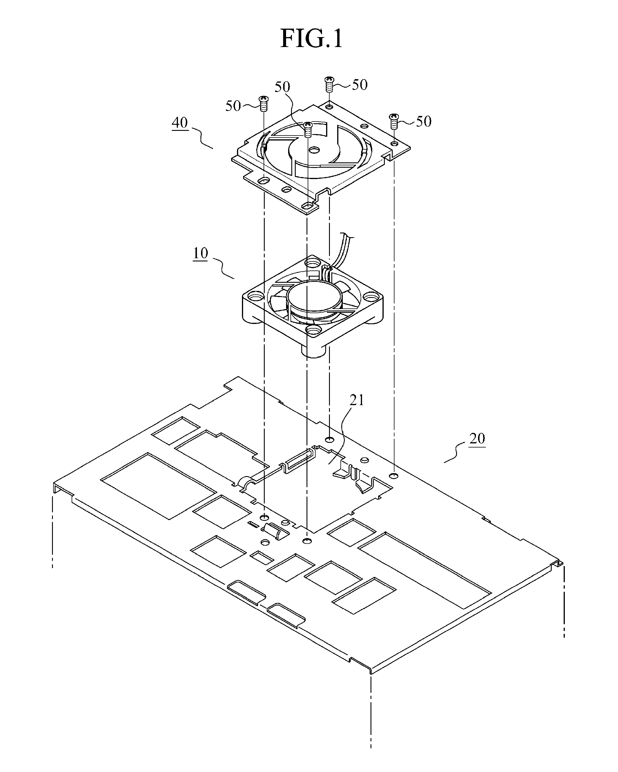
[0021]FIG. 1 is an assembly and exploded view of a fan fastening device in accordance with a first embodiment of the present invention.

[0022]During assembly, a heat dissipating fan 10 is housed in an opening 21 of a chassis 20 and fitted therein, a holder 40 is placed over the upper portion of the heat dissipating fan 10, and the periphery of the holder 40 is fixed to the chassis 20 with screws 50. In this case, the chassis 20 and the holder 40 each having a structure as discussed hereinbelow can bring about a state where the heat dissipating fan 10 is securely mounted therein.

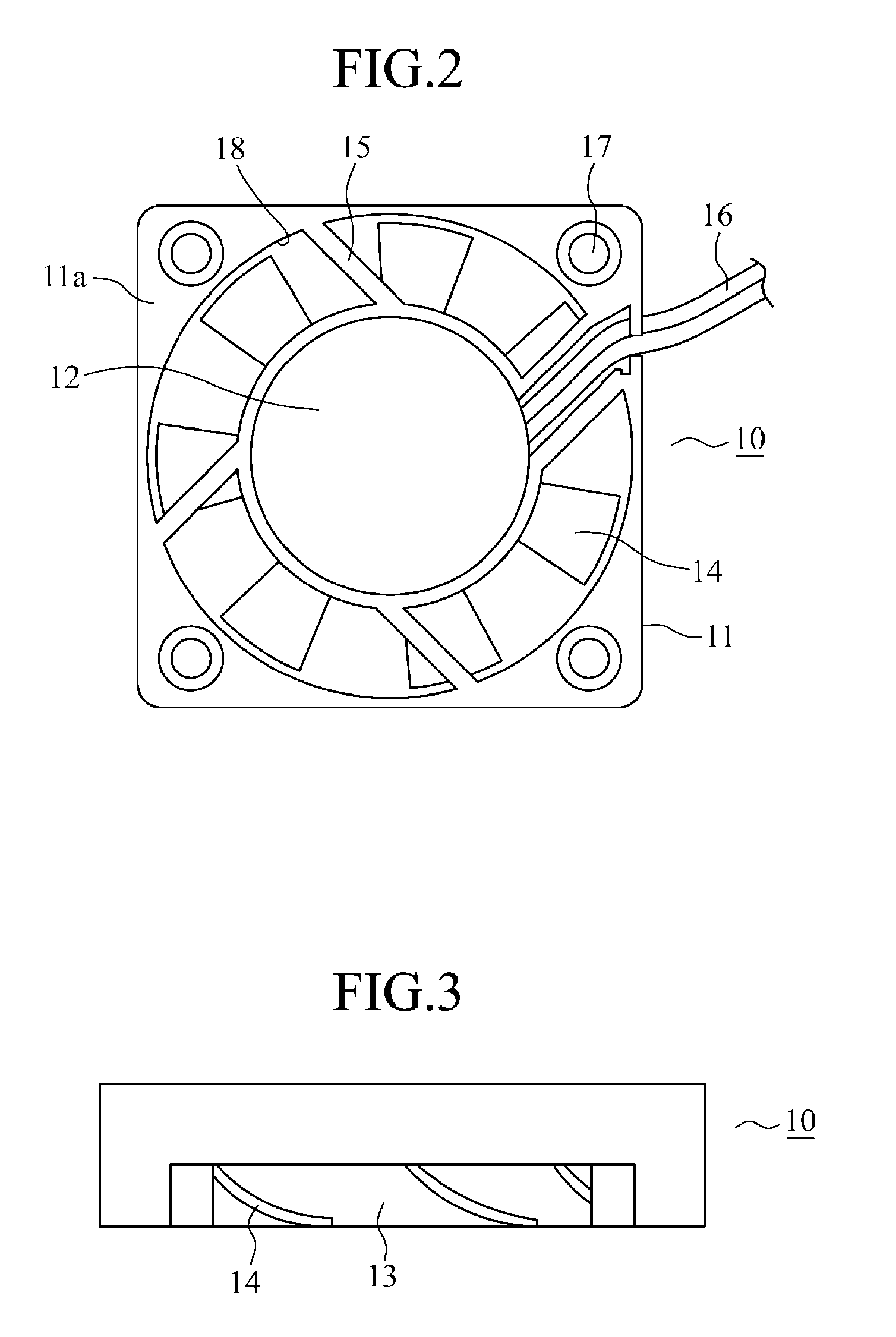
[0023]First, a structure of the heat dissipating fan 10 will be discussed by referring to FIG. 2 and FIG. 3.

[0024]Though the heat dissipating fan 10 employed herein is a commercially available standard product, even different manufacturers can provide the fan having a substantially similar structure. The heat dissipating fan 10 is molded from plastic except parts related to the rotation of a motor (not shown) ...


PUM


Abstract

A heat dissipating fan is housed in the opening of a chassis in the direction of thickness of the fan; a plurality of holding portions provided on the edges of the opening support the heat dissipating fan, parallel to the surface of the chassis; a plurality of elastic members provided on the two adjoining edges of the opening, respectively, urge the heat dissipating fan in the respective directions of the opposed edges of the opening to position the fan; and further a holder is provided with a plurality of elastic portions around ventilating openings corresponding to a blower window of the heat dissipating fan, and the elastic portions are abutted against the top surface of the peripheral portion of an outer casing of the heat dissipating fan to urge the heat dissipating fan perpendicularly to the face of the chassis.

Description

TECHNICAL FIELD[0001]The present invention relates to a fan fastening device for fastening a heat dissipating fan that ventilates the interior of an electronics equipment to a chassis.BACKGROUND ART[0002]Integrated circuits are employed for a large number of electronic circuits in today's electronics for the purpose of downsizing; however, a circuit, a disk drive, and the like are housed within a narrow space thereof. Thus, heat from an element generating a large amount of heat such as a CPU (central processor unit) is accumulated within an electronics equipment, which can become a factor causing a CPU itself and other integrated circuits to malfunction. For this reason, a fan for dissipating heat accumulated in the interior thereof to the exterior is installed in a large number of electronics equipments. In general, a variety of commercially available large or small fans, which are reduced in weight, are used as heat dissipating fans, and electronics makers install those fans in th...

Claims


Application Information

Patent Timeline
Patent Type & Authority Patents(United States)
IPC IPC(8): H05K7/20
CPCF04D25/0613F04D29/601
Inventor HIROTA, HIDEYUKI
Owner MITSUBISHI ELECTRIC CORP
Why Eureka
Try Eureka