Earphone antenna device

a technology for earphone antennas and antennas, which is applied to antenna equipments with additional functions, antennas, and antennas. it can solve the problems of degrading the antenna performance, increasing the manufacturing cost of products, and inconvenient carrying of broadcast receiving antennas, so as to reduce noise and improve the antenna performance of products.

Inactive Publication Date: 2013-02-21
SAMSUNG ELECTRONICS CO LTD
View PDF6 Cites 2 Cited by
  • Summary
  • Abstract
  • Description
  • Claims
  • Application Information

AI Technical Summary

Benefits of technology

[0016]Accordingly, an aspect of the present invention is to provide an earphone antenna device configured to use an antenna line in place of an earth line and without using the earth line on an earphone antenna cable to remove a need for the conventional earphone signal earth line in the earphone antenna cable, thereby reducing noises, which have been generated between the antenna line and the conventional earphone signal earth line, and improving the antenna performance of a product.

Problems solved by technology

To this end, the broadcast receiving antenna has to be inconveniently carried at all times with the portable communication device.
However, the conventional earphone antenna includes an earphone signal earth line in adjacent to an antenna line, such that noise signals induced to the earth lines are delivered to the antenna line, thus degrading the performance of the antenna.
Moreover, when the microphone line, the left and right speaker lines, the earphone signal earth lines, and the antenna line are covered in a single cable, the diameter of the cable increases, thereby causing the design of a product to be unattractive, increasing the manufacturing cost of the product, and degrading the flexibility of the product which in turn degrades the wearing sense of the product.
Furthermore, the volume of the earphone cable increases, so there is a problem that it requires a large storage space according to the increased volume of the earphone cable.

Method used


Image

  • Earphone antenna device
  • Earphone antenna device
  • Earphone antenna device

Examples


Embodiment Construction

[0028]Hereinafter, an exemplary embodiment of the present invention will be described with reference to the accompanying drawings. For the purposes of clarity and simplicity, well known structures or components will not be described as they obscure the subject matter of the present invention.

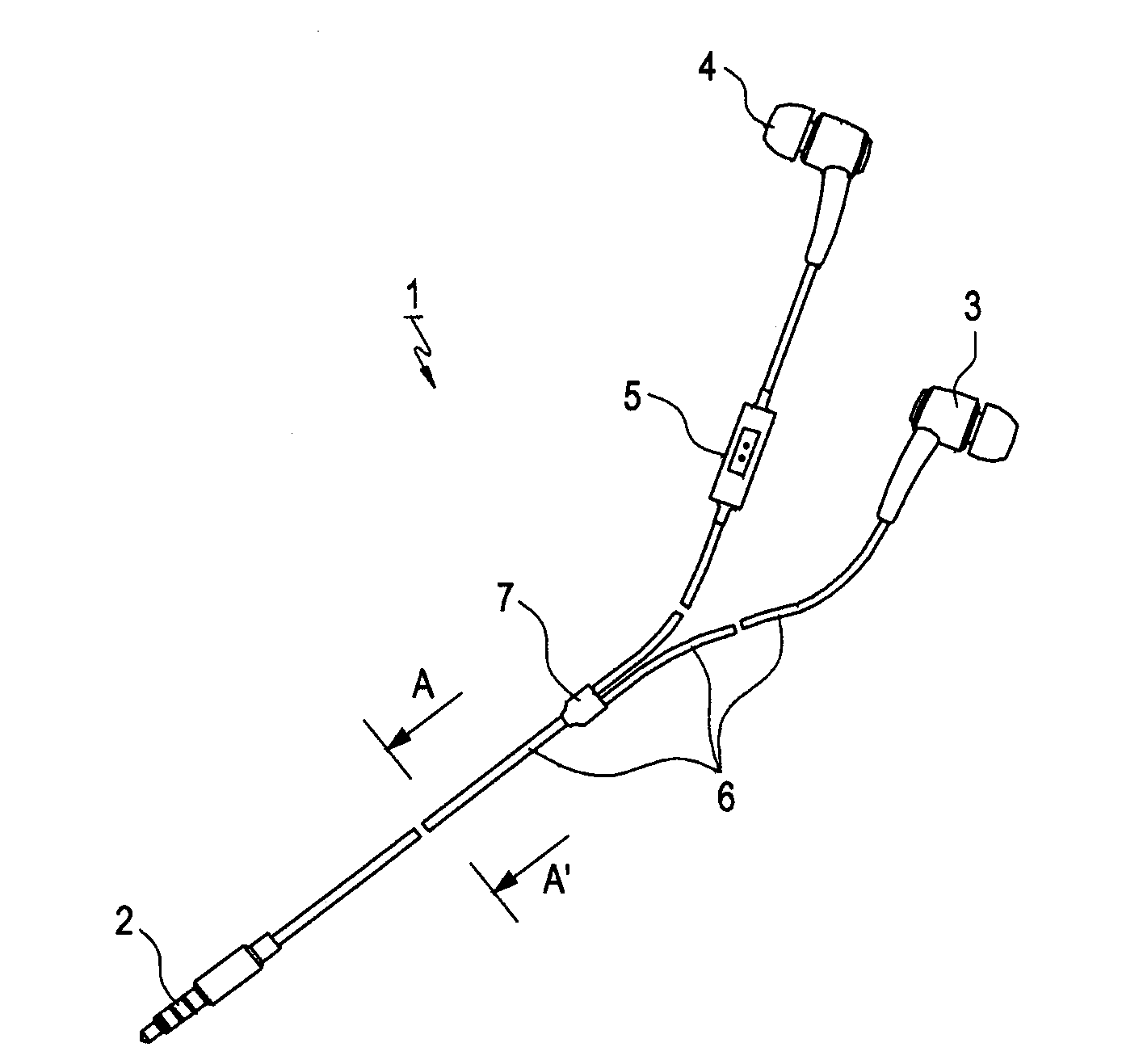
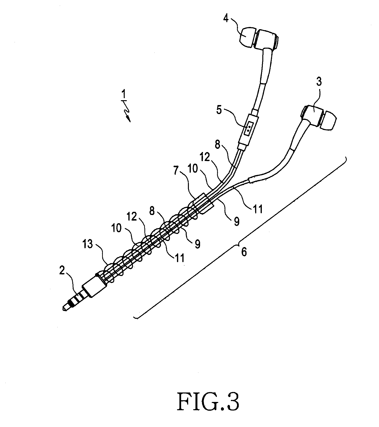
[0029]Referring to FIGS. 4 through 6, an earphone antenna device 100 according to an embodiment of the present invention may include an ear jack 101, a junction 102, left and right speaker phones 103 and 104, a microphone device 105, first and second cables 200 and 210, and a bead portion 220.

[0030]Herein, the ear jack 101 may be a 3.5Ø ear jack.

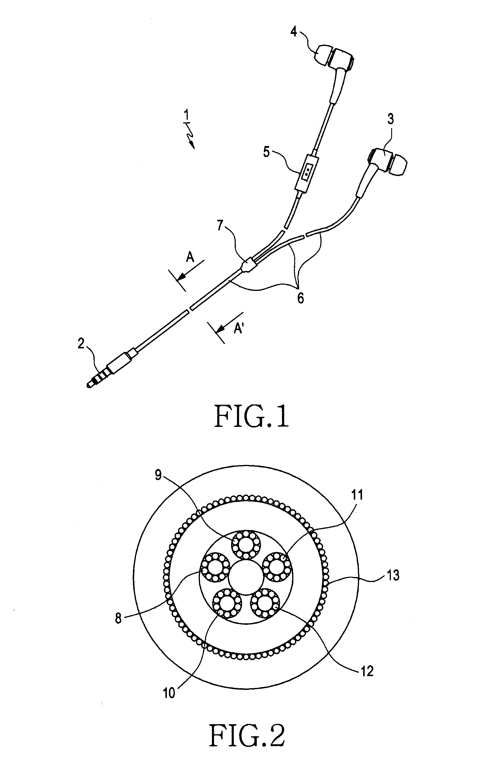
[0031]Referring to FIGS. 5 and 6, in this state, between the ear jack 101 and the junction 102 is provided a first cable 200 which has embedded therein an antenna line 214 having a function as the earth line. That is, the antenna line 214 serves to function as the earth line, thus eliminating the need of the conventional earth line. The earth line may be...


PUM


Abstract

Provided is an earphone antenna device configured to use an antenna line in lieu of a ground line in a specified area of an earphone antenna cable, and more specifically the earphone antenna device o includes a first cable provided between an ear jack and an junction to have embedded therein an antenna line used without comprising the earth line, a second cable embedded therein a plurality of earth lines, wherein a bead portion embedded in the junction to electrically couple the antenna line and the plural earth lines.

Description

CLAIM OF PRIORITY[0001]This application claims the benefit under 35 U.S.C. §119 of a Korean Patent Application filed in the Korean Intellectual Property Office on Aug. 17, 2011 and assigned Serial No. 10-2011-0081913, the entire disclosure of which is hereby incorporated by reference.BACKGROUND OF THE INVENTION[0002]1. Field of the Invention[0003]The present invention relates to an earphone antenna having an antenna line and an earth line as an earphone antenna cable.[0004]2. Description of the Related Art[0005]Generally, an earphone is coupled to an audio output jack of a portable communication device, a radio set, a Portable Multimedia Player (PMP), an MP3 player, a cassette player, a Compact Disc (CD) player, a Digital Multimedia Broadcasting (DMB) player, a portable terminal, etc., to transmit an audio signal to an earphone for replay.[0006]Recently, as terrestrial DMB and satellite DMB functions have been added to portable communication devices, users on the move can now enjoy ...

Claims


Application Information

Patent Timeline
Patent Type & Authority Applications(United States)
IPC IPC(8): H01Q1/44
CPCH01Q1/27H01Q1/44H01Q1/22H01Q1/48H04R1/10
Inventor KIM, TAE-ILCHO, IN-SUNGGHIM, JAE-GON
Owner SAMSUNG ELECTRONICS CO LTD
Why Eureka
Try Eureka