Top-Emissive Organic Light-Emitting Diode Display

a technology of organic light-emitting diodes and display panels, which is applied in the direction of organic semiconductor devices, semiconductor devices, electrical devices, etc., can solve the problems of uneven brightness of display devices across the entire screen, image quality problems, and uneven cathode voltages, etc., to reduce cathode resistance and reduce manufacturing time and costs.

Active Publication Date: 2019-07-04
LG DISPLAY CO LTD
View PDF0 Cites 7 Cited by
  • Summary
  • Abstract
  • Description
  • Claims
  • Application Information

AI Technical Summary

Benefits of technology

[0020]The organic light-emitting diode display according to the present disclosure is provided as a large-area organic light-emitting diode display in which an auxiliary cathode is formed by using a shielding layer for protecting a metal oxide semiconductor material from light coming from the outside. The auxiliary cathode and the cathode may be physically and electrically connected, without an additional mask process, by forming an under-cut structure in a passivation film patterning process. The present disclosure provides a large-area organic light-emitting diode display because of its structure capable of reducing the resistance of the cathode. Moreover, the manufacturing time and costs can be reduced by reducing the number of mask processes.

Problems solved by technology

Although there is no problem when the cathode is made of a metal material with low resistivity, there may be problems with image quality if the cathode is made of a transparent conductive material, due to its high surface resistance.
As a result, the voltage of the cathode may not be constant across the entire area of the display panel.
The uneven brightness of the display device across the entire screen may become a more important issue, especially in the development of large-area organic light-emitting diode displays.

Method used


Image

  • Top-Emissive Organic Light-Emitting Diode Display
  • Top-Emissive Organic Light-Emitting Diode Display
  • Top-Emissive Organic Light-Emitting Diode Display

Examples


first exemplary embodiment

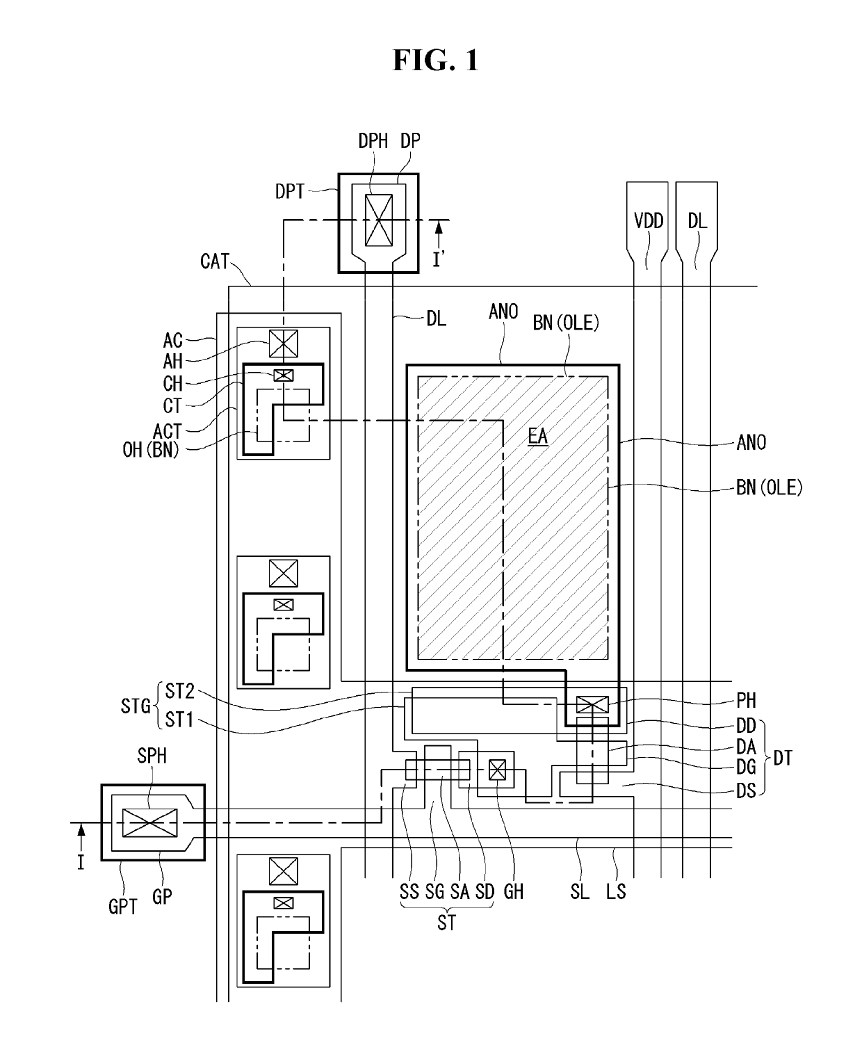
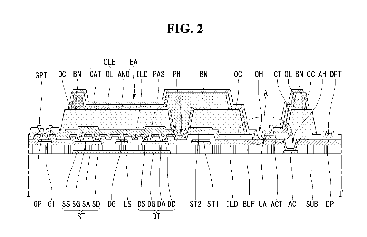
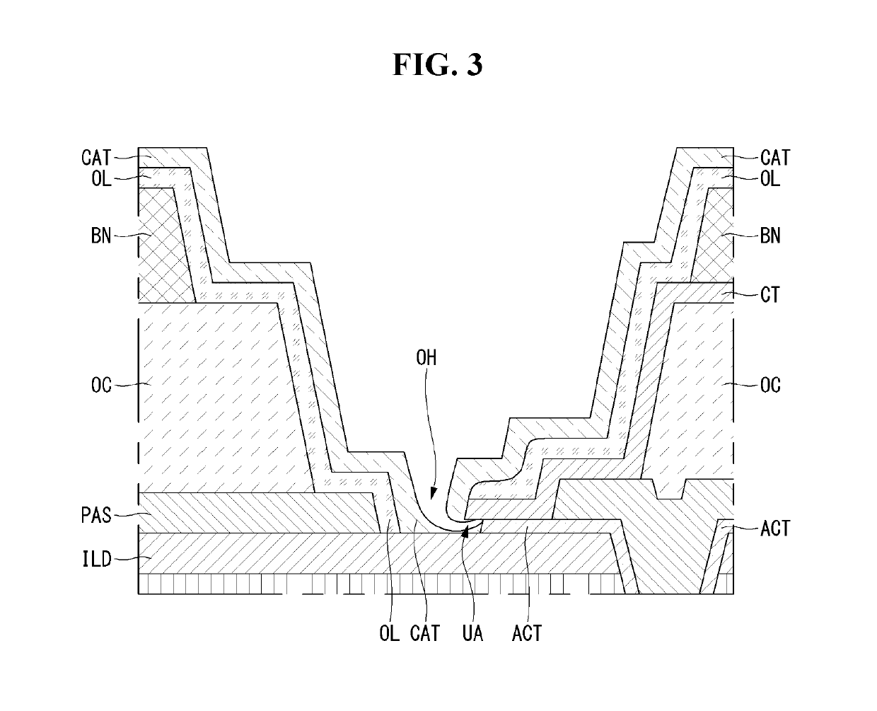
[0035]Hereinafter, a structure of an organic light-emitting diode display according to a first exemplary embodiment of the present disclosure will be described with reference to FIGS. 1 to 3. FIG. 1 is a plan view of a structure of an organic light-emitting diode display according to the present disclosure. FIG. 2 is a cross-sectional view of the organic light-emitting diode display according to the first exemplary embodiment of the present disclosure, taken along the line I-I′ in FIG. 1. FIG. 3 is an enlarged cross-sectional view of a structure of the under-cut opening of FIG. 2 where the cathode and auxiliary cathode are connected.

[0036]The organic light-emitting diode display according to the first exemplary embodiment of the present disclosure comprises a plurality of pixel regions arranged in a matrix on a substrate SUB. The organic light-emitting diode display comprises a scan line SL that runs horizontally on the substrate SUB and a data line DL and a drive current line VDD t...

second exemplary embodiment

[0066]Hereinafter, a second exemplary embodiment of the present disclosure will be described with reference to FIG. 5. The basic configuration of an organic light-emitting diode display according to the second exemplary embodiment is identical to that of the first exemplary embodiment. The only difference is the structure of part of the under-cut opening OH. Thus, the description below focuses on the structure of the under-cut portion. The description will be given referring again to FIG. 1 because no difference is found on the plane. The manufacturing process also is identical to that of the first exemplary embodiment, except for the difference in the type of material used. Thus, a description of the process, if required, will be given referring to the drawings of the first exemplary embodiment. FIG. 5 is an enlarged cross-sectional view of a structure of an under-cut opening where a cathode and an auxiliary cathode are connected, in an organic light-emitting diode display accordin...


PUM


Abstract

The present disclosure relates to a top-emissive organic light-emitting diode display. The organic light-emitting diode comprises a substrate, an auxiliary cathode, a passivation film, a planarization film, an under-cut opening, a connecting terminal, an under-area, a bank, an organic emission layer, and a cathode. The auxiliary cathode is placed on the substrate. The connecting terminal makes contact with the top surface of the one end exposed through the under-cut opening and protrudes into the under-cut opening, being longer in length than the one end of the auxiliary cathode. The under-area is formed between the end of the connecting terminal and the one end of the auxiliary cathode. The cathode is stacked on the organic emission layer, makes contact with the side of the connecting terminal not covered by the organic emission layer, and extends all the way to the under-area.

Description

[0001]This application claims the benefit of Republic of Korea Patent Application No. 10-2017-0182076 filed on Dec. 28, 2017, which is incorporated herein by reference in its entirety.BACKGROUND DISCLOSUREField of Disclosure[0002]The present disclosure relates to a top-emissive organic light-emitting diode display. More particularly, the present disclosure relates to a top-emissive organic light-emitting diode display that comprises an auxiliary cathode for reducing the surface resistance of a cathode and has an under-cut structure configured to directly connect the auxiliary electrode and the cathode.Related Art[0003]Recently, various flat-panel displays that are less bulky and more lightweight than cathode ray tubes (CRTs) are being developed. Examples of these flat panel displays include liquid crystal displays (LCDs), field emission displays (FEDs), plasma display panels (PDPs), electroluminescence devices (ELs), etc.[0004]Electroluminescence displays are roughly classified into...

Claims


Application Information

Patent Timeline
Patent Type & Authority Applications(United States)
IPC IPC(8): H01L51/56H01L27/32H01L51/52H01L51/10
CPCH01L51/56H01L27/3295H01L27/3248H01L51/5206H01L51/5228H01L51/5237H01L51/105H01L27/3246H01L51/5253H01L2251/5315H01L27/3244H01L27/3258H01L27/3276H01L27/3272H01L27/3223H10K59/12H10K50/824H10K2102/3026H10K59/122H10K59/124H10K59/1315H10K59/35H10K59/1213H10K50/805H10K50/82H10K50/844H10K10/84H10K50/81H10K50/84H10K59/88H10K59/123H10K59/126H10K59/131H10K71/00
Inventor LEE, JAESUNGYOO, SEUNGWONLEE, JOONSUK
Owner LG DISPLAY CO LTD
Why Eureka
Try Eureka