Rotary feeding member, sheet feeding apparatus and image forming apparatus

Active Publication Date: 2019-07-25
CANON KK
View PDF8 Cites 0 Cited by
  • Summary
  • Abstract
  • Description
  • Claims
  • Application Information

AI Technical Summary

Benefits of technology

The invention relates to a rotary feeding member for a sheet feeding apparatus or an image forming apparatus. The rotary feeding member has protruding portions that are in contact with the sheet and first recessed portions between the protruding portions. The first recessed portions are recessed to a first depth with respect to the outer surface of the rotary feeding member. Additionally, the rotary feeding member has second recessed portions between the protruding portions that are recessed to a second depth smaller than the first depth. The invention aims to improve the feeding performance of the rotary feeding member by optimizing the contact between the sheet and the feeding member.

Problems solved by technology

However, the surface of the roller is gradually worn out after repeated sheet conveyance, so the roller is required to be replaced at an appropriate time.
However, the inventors of the present disclosure have found, through an endurance test where sheets were repeatedly fed while the actual detection time of the sheets were measured, that the change of conveyance efficiency with respect to the amount of wear has little linearity, and that there were cases where the conveyance efficiency was deteriorated acutely after a certain number of sheets were fed.
In such case, the end of life of the roller is not easily predicted in advance, and there were cases where sheet jam started to occur frequently when wear of the roller was detected based on the detection time.

Method used


Image

  • Rotary feeding member, sheet feeding apparatus and image forming apparatus
  • Rotary feeding member, sheet feeding apparatus and image forming apparatus
  • Rotary feeding member, sheet feeding apparatus and image forming apparatus

Examples


first embodiment

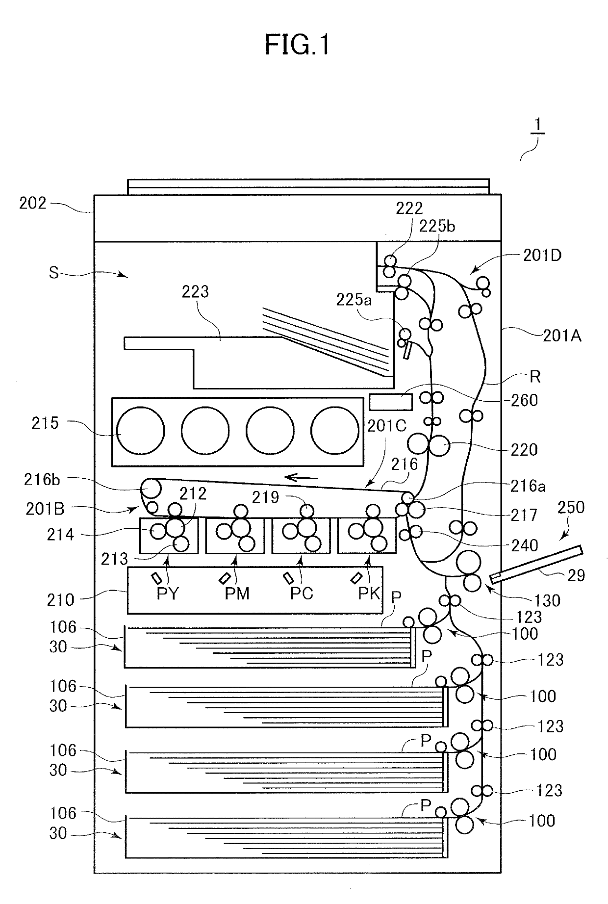
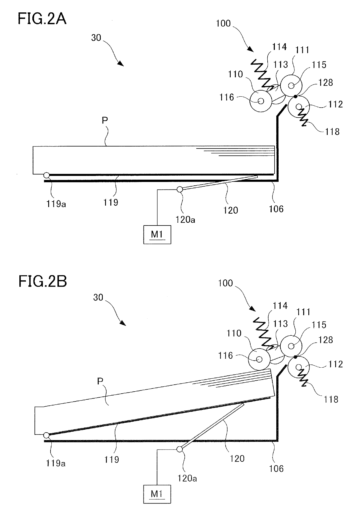
[0056]A roller serving as a rotary feeding member according to a first embodiment and a method for detecting end-of-life signal thereof will be described with reference to FIGS. 6 through 12. A roller 101 according to the present embodiment is used for either one of or both the pickup roller 110 and the feed roller 111 in the sheet feeding portion 30 described above.

[0057]As illustrated in FIG. 6, the roller 101 is composed of an outer portion 133 formed of rubber material and a core 134 formed of synthetic resin. The core 134 is detachably attached to a roller shaft. The cylindrical outer portion 133 rotates together with the core 134 in a state attached on the outer circumference of the core 134. A knurling, that is, a pattern where regular protrusions and recesses appear repeatedly in a circumferential direction, is formed on the surface of the outer portion 133.

[0058]FIG. 7A is a cross-sectional view illustrating the roller 101 viewed in a width direction, which is the same as a...

modified examples

[0088]Methods other than detecting the deterioration of conveyance efficiency based on the sheet arrival time to the conveyance sensor 130 may be used as the method for detecting end-of-life signal. For example, a configuration can be adopted where an optical sensor for detecting whether a surface of the roller 101 has protrusions and recesses having a predetermined depth or greater is provided, and end of life is determined to be near if it is determined that the B-regions has become smooth, that is, the depth of the protrusions and recesses have become smaller than a threshold value. Further, instead of adopting a configuration where the controller 260 automatically executes end-of-life signal detection, it may be possible to adopt a configuration where a user or a maintenance personnel determines through visual confirmation whether knurling in the B-regions of the roller 101 still exists (refer to FIG. 9A). In this case, a mark may be embedded in the B-regions that is not visible...

second embodiment

[0092]Now, a second embodiment will be described with reference to the drawings of FIG. 13. According to the present embodiment, a surface shape of a roller 201 used as a rotary feeding member differs from the first embodiment. The other common elements as the first embodiment are denoted with the same reference numbers as the first embodiment and descriptions thereof are omitted.

[0093]FIG. 13A is a perspective view of the roller 201 according to the present embodiment. The roller 201 includes a core 234 and an outer portion 233, and similar to the roller 101 of the first embodiment, it can be adopted to either one of or both the pickup roller 110 and the feed roller 111 of the sheet feeding portion 30.

[0094]As illustrated in FIG. 13B, a crest portion 238 that is a lattice-shaped projected structure and a plurality of recessed portions 235 in the form of rectangular cells defined by the crest portion 238 are provided on the surface of the outer portion 233. As illustrated in the cro...


PUM


Abstract

A rotary feeding member for feeding a sheet is provided with a plurality of protruding portions, a plurality of first recessed portions and a plurality of second recessed portions on a cross-section perpendicular to a width direction of the rotary feeding member. The plurality of protruding portions constituting an outer circumferential surface of the rotary feeding member to be in contact with the sheet. Each of the plurality of first recessed portions and the plurality of second recessed portions is provided between any adjacent two of the plurality of protruding portions in the rotating direction. The plurality of first recessed portions are recessed to a first depth with respect to the outer circumferential surface, and the plurality of second recessed portions are recessed to a second depth smaller than the first depth with respect to the outer circumferential surface.

Description

BACKGROUND OF THE INVENTIONField of the Invention[0001]The present invention relates to a rotary feeding member for feeding sheets by rotating in contact with the sheet, a sheet feeding apparatus equipped with the rotary feeding member, and an image forming apparatus for forming an image on a sheet.Description of the Related Art[0002]In image forming apparatuses such as printers, copying machines and multifunction printers, sheet feeding apparatuses for feeding sheets as recording media or original documents are equipped with rotary feeding members such as rollers for feeding sheets by rotating in contact with the sheets. In many cases, a surface of the roller is formed of a material such as rubber that has a high friction coefficient with respect to sheets, and sheets are conveyed by friction between the surface of the roller and the sheet by rotation of the roller. However, the surface of the roller is gradually worn out after repeated sheet conveyance, so the roller is required t...

Claims


Application Information

Patent Timeline
IPC IPC(8): B65H5/06
CPCB65H5/06B65H2513/52B65H2557/35B65H2601/121B65H3/0638B65H2404/1115B65H2404/1118B65H2404/1119B65H27/00
Inventor CHIBA, YOSHINAO
Owner CANON KK
Why Eureka
Try Eureka