
Communications network

a communication network and network technology, applied in the field of aviation, can solve the problems of relatively burdensome architecture and achieve the effect of ensuring the independence of exchanged data

Active Publication Date: 2019-10-10
SAFRAN ELECTRONICS & DEFENSE
View PDF0 Cites 0 Cited by
  • Summary
  • Abstract
  • Description
  • Claims
  • Application Information

AI Technical Summary

Benefits of technology

This patent describes a switch that allows data to be shared between different modules and user terminals while maintaining privacy and independence. The switch has multiple configurations that can be used simultaneously without interfering with data streams. Additionally, users can modify their own terminal characteristics without changing the entire switch.

Problems solved by technology

Such a communications network thus presents an architecture that is relatively burdensome and that includes in particular a large number of switches.

Method used


Image

  • Communications network
  • Communications network
  • Communications network

Examples


Embodiment Construction

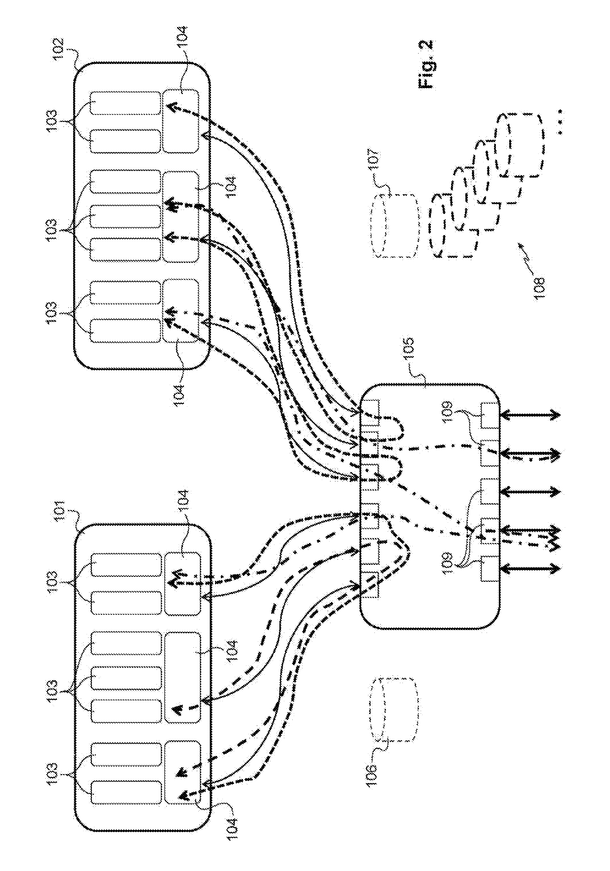
[0027]With reference to FIG. 2, the communications network in a particular embodiment of the invention is a communications network for aircraft.

[0028]In this example, the communications network includes a first module 101 and a second module 102, each associated with an avionics element of the aircraft (not shown). By way of example, each module 101, 102 is a computer or a processor or a set of computers and / or processors. Each module hosts multiple avionics applications / functions 103 that are to be executed, which applications / functions 103 are specific to the avionics element associated with said module. Each module also includes connection units 104, each associated with one or more applications / functions 103 of said module. In this example, the connection units 104 are of the ARINC 664 P7 End System type.

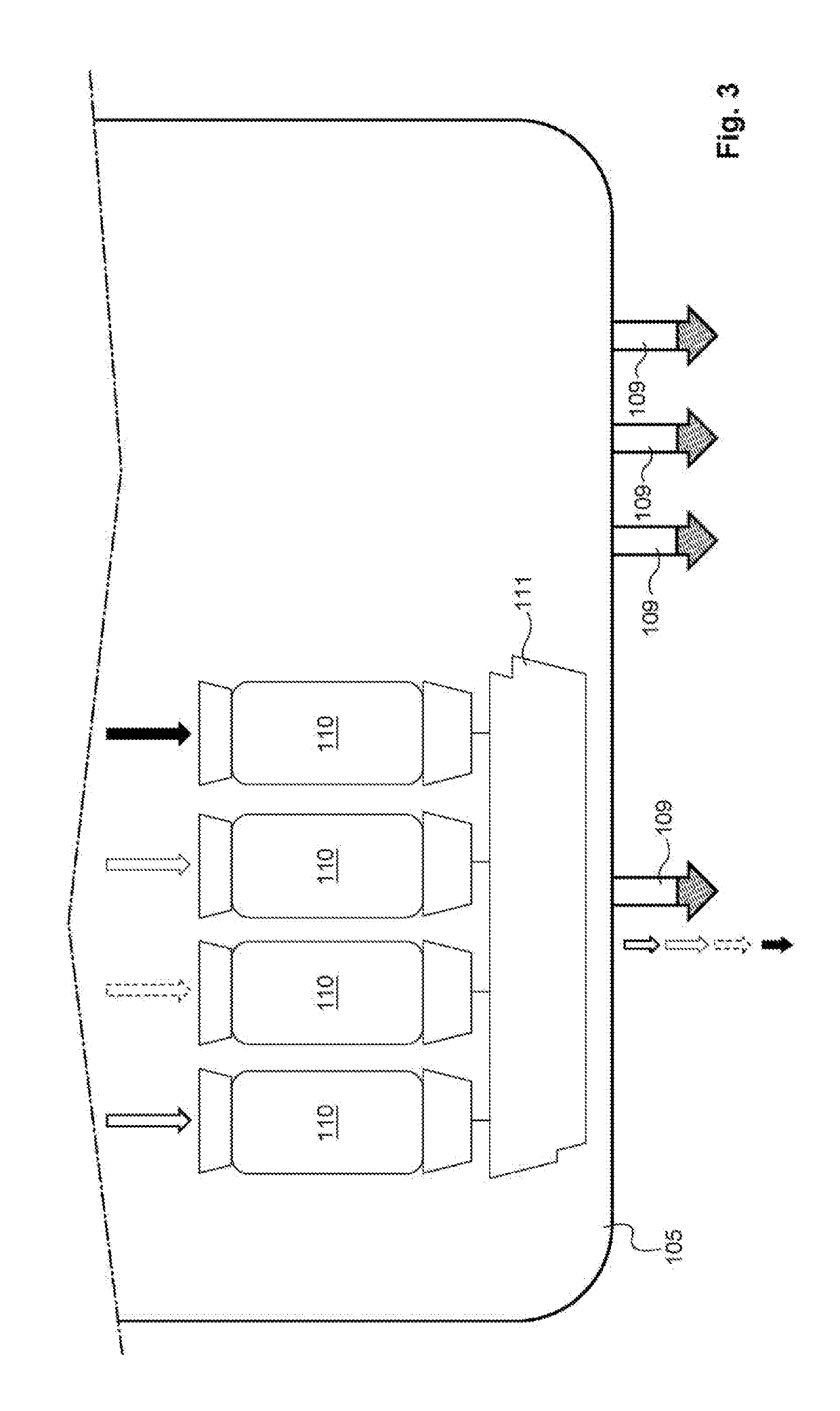
[0029]The communications network also includes a switch 105 that is shared firstly between the various modules 101, 102, and secondly between various user terminals (not shown)....


PUM


Abstract

The invention provides a communications network comprising at least two modules and a common switch connected firstly to the two modules and secondly to various different user terminals, the switch having as many configurations as there are user terminals and modules connected to the switch, each user terminal and each module being associated with a particular dedicated configuration.

Description

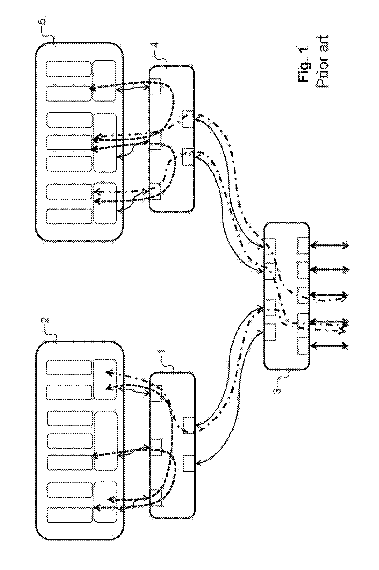
[0001]The invention relates to a communications network, and particularly but not exclusively to a communications network for aircraft.TECHNOLOGICAL BACKGROUND OF THE INVENTION[0002]In the field of aviation, communications networks serve to convey communications that are internal to an airplane, which communications serve mainly to exchange data between various elements of the avionics or even within a single element of the avionics.[0003]Usually, a communications network has modules (computers, processors, . . . ) that are put into communication with user terminals via switches in order to exchange data within a given module or between a module and a user terminal, the switches being configured to monitor and distribute the various data frames of the various logical channels of the network on the basis of configuration tables containing the characteristics specific to each logic channel and to each outlet port associated with the switch in question.[0004]FIG. 1 is a diagram of a pr...

Claims


Application Information

Patent Timeline
Patent Type & Authority Applications(United States)
IPC IPC(8): H04L12/24H04L49/111
CPCH04L29/08H04L41/0823H04L12/28H04L67/12H04L41/082H04L41/0856H04L12/40006H04L65/40
Inventor TOILLON, PATRICEGUILLOT, FRANCOIS
Owner SAFRAN ELECTRONICS & DEFENSE
Learn More