Light emitting display apparatus

Active Publication Date: 2019-11-14
LG DISPLAY CO LTD
View PDF0 Cites 7 Cited by
  • Summary
  • Abstract
  • Description
  • Claims
  • Application Information

AI Technical Summary

Benefits of technology

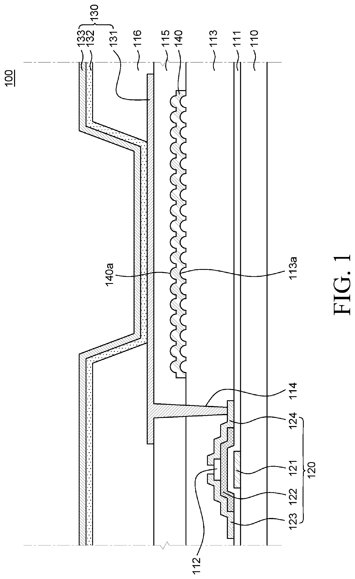
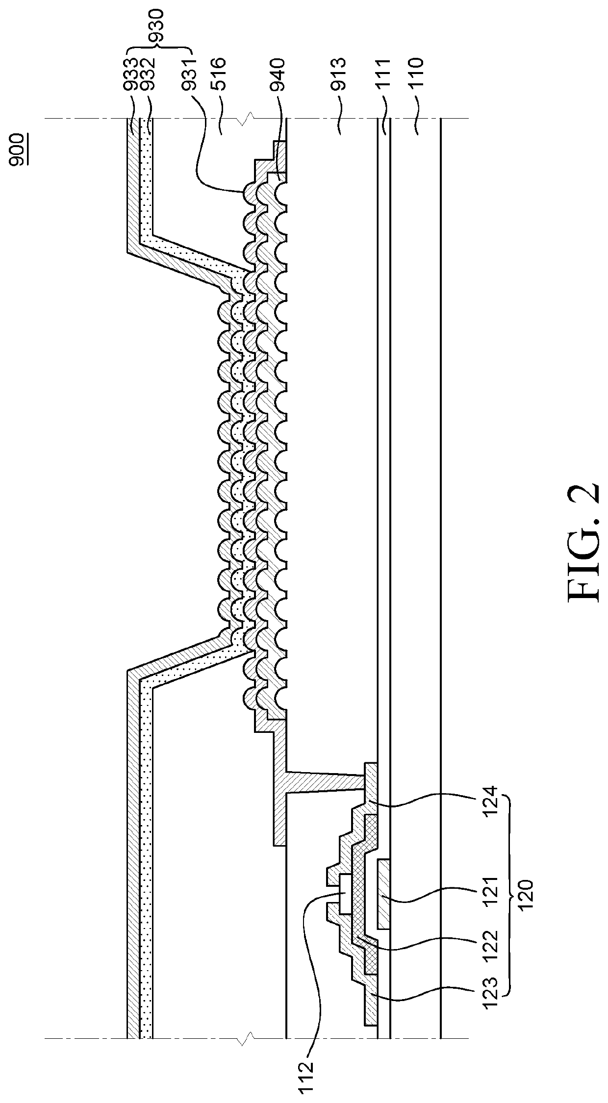
The present invention introduces a new structure for a light emitting display that minimizes the loss of surface plasmon, which helps to enhance the efficiency of light extraction.

Problems solved by technology

However, some of the light emitted from the light emitting layer may not be output to the outside of the light emitting display apparatus but may be confined inside the light emitting display apparatus so that the light extracting efficiency of the light emitting display apparatus becomes an issue.
For example, there is a limitation in that some light among the light emitted from the light emitting layer of the light emitting display apparatus according to the related art can be confined in the light emitting display apparatus due to a total reflection loss, a waveguide loss, and a surface plasmon loss.
The waveguide loss refers to the degradation of light extracting efficiency due to the light confined therein due to the total reflection at the interface of components in the light emitting display apparatus.
The surface plasmon loss refers to a situation when the light vibrates free electrons of the metal surface due to a phenomenon that light is absorbed onto a metal surface during a process of entering and propagating the light so that the light cannot be reflected or transmitted, which in turn degrades the light extracting efficiency.
Further, the inventor of the present disclosure found out that when the light emitting element is formed on an uneven surface, the light emitting element may be formed to have an uneven shape and when configurations of the light emitting element are uneven, the reliability of the light emitting element may be degraded due to irregular electricity injection onto the uneven light emitting layer.
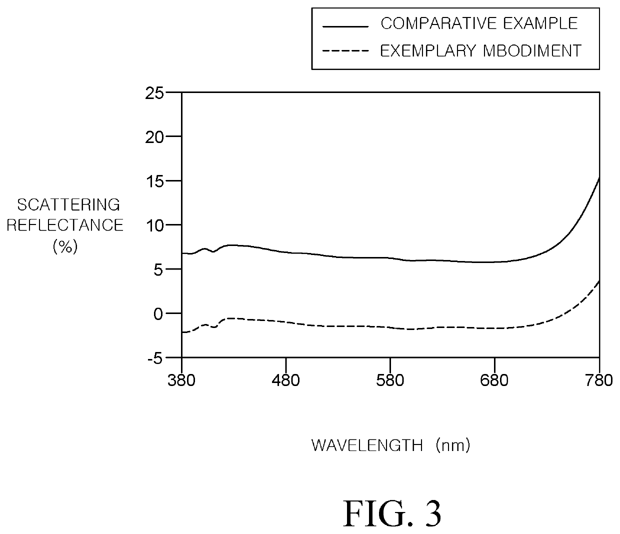
The inventor of the present disclosure found out that when the light emitting element is manufactured to be uneven, there is a problem in that scattering reflectance in an off-state of the light emitting display apparatus is increased so that a luminosity in an off-state, that is, a black luminosity may be degraded and thus not only the outdoor visibility, but also the contrast ratio can be degraded.

Method used


Image

  • Light emitting display apparatus
  • Light emitting display apparatus
  • Light emitting display apparatus

Examples


Embodiment Construction

[0035]Advantages and characteristics of the present disclosure and a method of achieving the advantages and characteristics will be clear by referring to exemplary embodiments described below in detail together with the accompanying drawings. However, the present disclosure is not limited to the exemplary embodiments disclosed herein but will be implemented in various forms. The exemplary embodiments are provided by way of example only so that those skilled in the art can fully understand the disclosures of the present disclosure and the scope of the present disclosure. Therefore, the present disclosure will be defined only by the scope of the appended claims.

[0036]The shapes, sizes, ratios, angles, numbers, and the like illustrated in the accompanying drawings for describing the exemplary embodiments of the present disclosure are merely examples, and the present disclosure is not limited thereto. Like reference numerals generally denote like elements throughout the specification. F...


PUM


Abstract

A light emitting display apparatus includes a substrate, a first planarization layer on the substrate, a metal layer having an uneven surface and disposed on the first planarization layer, a second planarization layer covering the metal layer on the first planarization layer, and a light emitting element on the second planarization layer, wherein the second planarization layer is disposed between a bottom layer of the light emitting element and the metal layer so as to separate the bottom layer of the light emitting element from the metal layer.

Description

CROSS-REFERENCE TO RELATED APPLICATIONS[0001]This application claims the priority to Korean Patent Application No. 10-2018-0052569 filed on May 8, 2018, in the Korean Intellectual Property Office, the disclosure of which is incorporated herein by reference into the present application.BACKGROUNDField[0002]The present disclosure relates to a light emitting display apparatus, and more particularly, to a light emitting display apparatus which has an improved light extracting efficiency and is capable of ensuring element stability.Description of the Related Art[0003]Currently, as the world enters a full-scale information era, a field of a display apparatus which visually expresses electrical information signals has been rapidly developed and studies are continuing to improve performances and properties of various display apparatuses such as thin-thickness, light weight, and low power consumption.[0004]Among various display apparatuses, a light emitting display apparatus is a self-emitti...

Claims


Application Information

Patent Timeline
IPC IPC(8): H01L51/50H01L27/32
CPCH01L51/5012H01L27/3246H01L27/3276H01L27/156H10K59/124H10K50/813H10K50/822H10K50/854H10K50/856H10K2102/3026H10K50/11H10K59/122H10K59/131
Inventor KIM, NAMSU
Owner LG DISPLAY CO LTD
Why Eureka
Try Eureka