Device for controlling a power supply with DC DC splitting of the type including N interlaced paths

Inactive Publication Date: 2013-08-27
COMMISSARIAT A LENERGIE ATOMIQUE ET AUX ENERGIES ALTERNATIVES +1
View PDF6 Cites 5 Cited by
  • Summary
  • Abstract
  • Description
  • Claims
  • Application Information

AI Technical Summary

Benefits of technology

[0036]A particular object of the invention is therefore to handle the degraded efficiency

Problems solved by technology

Therefore, even though the wiring inductances are high, they no longer have an effect in the conversion.
But then, all the applications do not have the same power requirements.
Moreover, the power required by a given application may vary over time.
Although the level of loss of all the resonant circuits of

Method used


Image

  • Device for controlling a power supply with DC DC splitting of the type including N interlaced paths
  • Device for controlling a power supply with DC DC splitting of the type including N interlaced paths
  • Device for controlling a power supply with DC DC splitting of the type including N interlaced paths

Examples


Embodiment Construction

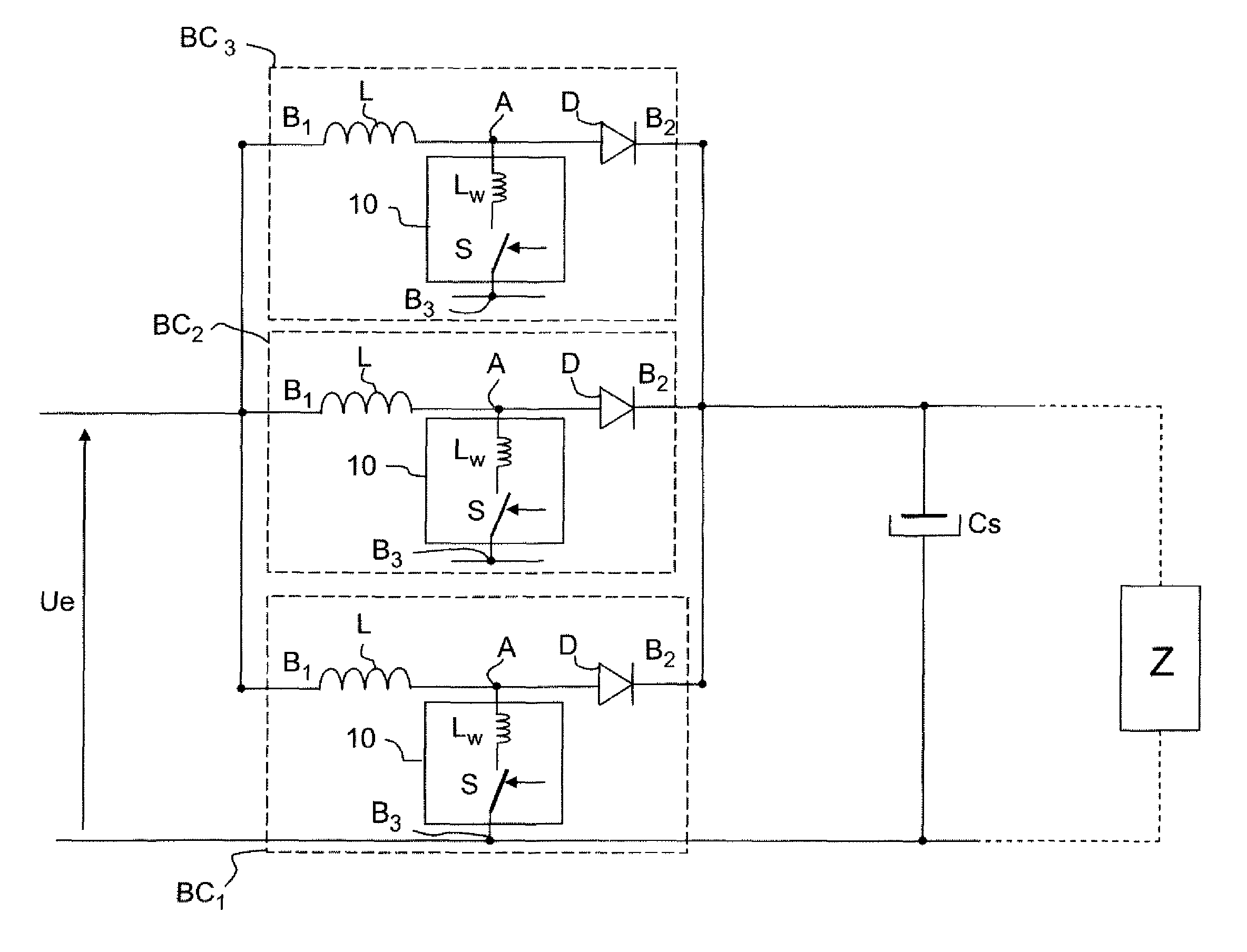
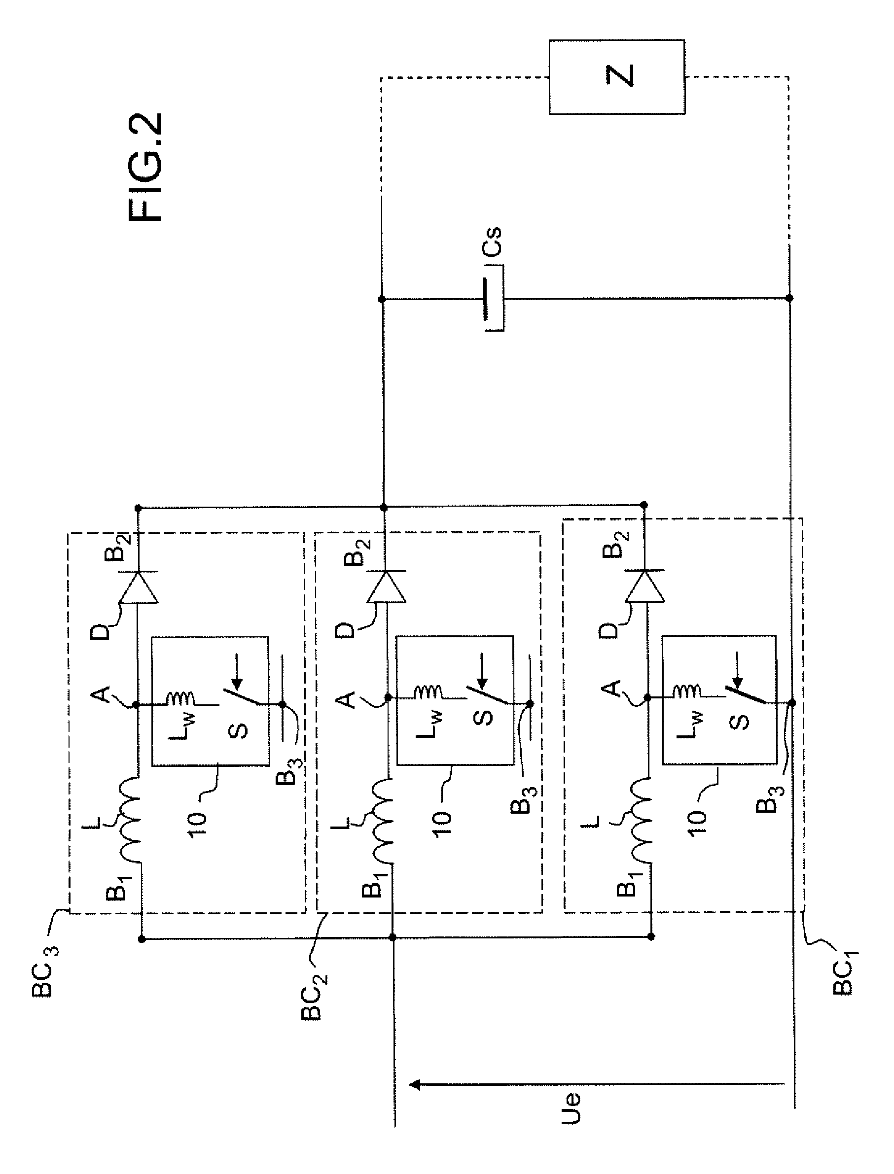
[0051]The invention applies to a non-isolated power supply with DC DC splitting with n interlaced cells BCi with n being an integer at least equal to 2. Advantageously it applies to a power supply with n interlaced cells, with resonance, as illustrated in FIG. 2.

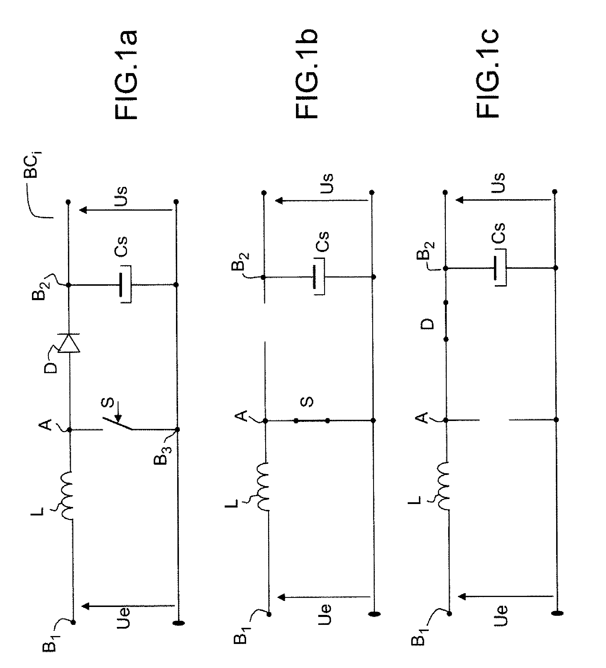
[0052]Each cell is comparable with a conversion path. This conversion path is active when, in a power supply conversion cycle, there is a phase of energy storage in the cell, obtained by the control to the closed state of the splitting switch S (FIGS. 2,3,4). The return to the open state triggers the output energy transfer stage. If the switch is never switched to the closed or on state, there is no energy storage phase and consequently there can be no energy transfer. The conversion path is inactive, or disabled.

[0053]According to the invention, and as illustrated in the schematic diagram of FIG. 11, it has been chosen to be able to activate all or some of the power supply paths conditionally, as a function of the power han...


PUM


Abstract

In a power supply with n interlaced conversion cells, a control device activates m paths out of n paths, 1≦m≦n, as a function of the power or of the current handled by the power supply. The cell may have a boost, buck, buck/boost, Cuk, or SEPIC topology.

Description

CROSS-REFERENCE TO RELATED APPLICATIONS[0001]This application is a National Stage of International patent application PCT / EP2009 / 053205, filed on Mar. 18, 2009, which claims priority to foreign French patent application No. FR 08 01575, filed on Mar. 21, 2008, the disclosures of which are incorporated by reference in their entirety.FIELD OF THE INVENTION[0002]The present invention relates to a power supply with DC DC splitting, with n interlaced paths, and more particularly a device for controlling such a power supply.[0003]The invention applies notably to the supply of a regulated direct-current voltage of determined level, based on the energy supplied by a fuel cell.BACKGROUND OF THE INVENTION[0004]Fuel cells are used in many applications. They are for example used as a source of energy in electric motor vehicles, or for recharging batteries, for example for recharging batteries of portable devices (telephones for example).[0005]Non-isolated power supplies with DC DC splitting, al...

Claims


Application Information

Patent Timeline
IPC IPC(8): G05F1/59G05F1/613
CPCH02M3/1584
Inventor CHATROUX, DANIELDOLHAGARAY, JEAN-CLAUDEROY, FRANCIS
Owner COMMISSARIAT A LENERGIE ATOMIQUE ET AUX ENERGIES ALTERNATIVES
Why Eureka
Try Eureka