Color OLED display with improved power efficiency

a technology of oled display and power efficiency, which is applied in the field of oled display devices with fullcolor, can solve the problems of insufficient display time, inability to meet the needs of users, so as to reduce overall power consumption, prolong the life of the display, and improve the luminance efficiency. the effect of luminance stability

Active Publication Date: 2005-09-29
GLOBAL OLED TECH
View PDF24 Cites 100 Cited by
  • Summary
  • Abstract
  • Description
  • Claims
  • Application Information

AI Technical Summary

Benefits of technology

[0017] In accordance with one embodiment, the present invention is directed towards a color OLED display device comprising: a) an array of light emitting pixels, each pixel having red, green, and blue OLEDs and at least one additional colored OLED that expands the gamut of the display device relative to the gamut defined by the red, green and blue OLEDs, wherein the luminance efficiency or the luminance stability over time of the additional OLED is higher than the luminance efficiency or the luminance stability over time of at least one of the red, green, and blue OLEDs; and b) means for selectively driving the OLEDs with a drive signal to reduce overall power usage or extend the lifetime of the display while maintaining display color accuracy.
[0018] In accordance with various embodiments, the present invention provides a color display device with improved power efficiency, longer overall lifetime, expanded color gamut with accurate hues, and improved spatial image quality.

Problems solved by technology

However, the known red and blue emissive materials do not have particularly high luminance efficiencies.
While power efficiency is always desirable, it is particularly desirable in portable applications because an inefficient display limits the time the device can be used before the power source is recharged.
However, this relationship may not always exist since it is plausible that the radiant efficiency of one of the light emitting elements can be significantly higher than the radiant efficiency of another light emitting element.
Similarly, to increase the color gamut, the peak wavelength of the red light emitting element must be increased, producing energy that is even longer in wavelength and further reducing the eye's sensitivity to the radiant energy provided by the light emitting element.
Therefore, to decrease the power consumption of a display device under typical use conditions, it is very important that colors near the white point of the display device consume as little power as possible.
Such different luminance stabilities can cause mismatched luminance efficiency changes to occur in the OLEDs over time, and limit the effective overall lifetime of the display device.
Unfortunately, utilizing a three to four color conversion using a three to four color matrix as described will result in inaccurate and desaturated primary colors.
While this body of art discusses the use of several methods to convert from three to four or more colors, there is no discussion of utilizing information such as the efficiency of a single emitter to perform the color conversion in a way that will result in lower power consumption while maintaining accurate colors.
While this patent does discuss the need to convert from an input three-color input signal to a four or more color signal, it does not describe a method to utilize these OLEDs in a way to reduce the power consumption of the display device.
However, since this method utilizes all four light emitting elements in a pixel to produce white, power consumption is not necessarily reduced.
In fact, these algorithms cannot be utilized to produce an accurate color conversion when the display device provides a fourth, gamut-expanding primary color.
The method described, however, does not provide a means for providing this conversion in a way to reduce the power consumption or extend the lifetime of an OLED display device.
The method is also inflexible in response to changing display conditions.
Further, the fact that using only three of the four light emitting elements can produce flat fields of color that do not appear uniform in luminance is also not discussed.

Method used


Image

  • Color OLED display with improved power efficiency
  • Color OLED display with improved power efficiency
  • Color OLED display with improved power efficiency

Examples


Embodiment Construction

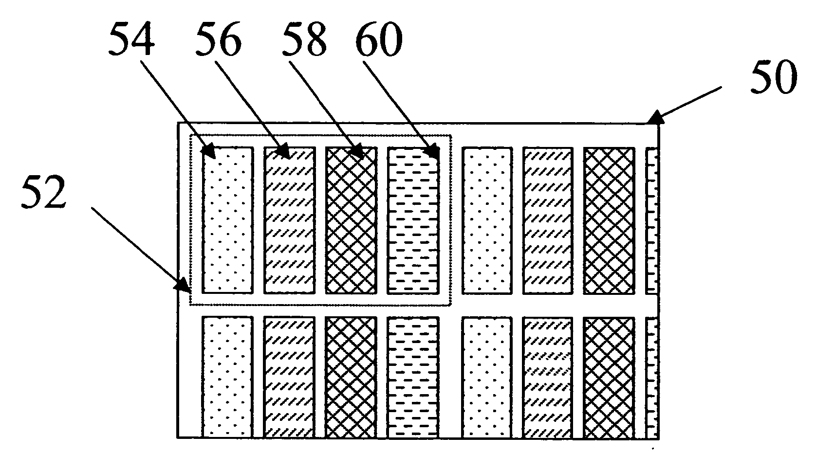
[0034] The present invention is directed to a full-color display device having a red, green, and blue OLED with one or more additional OLEDs that expand the color gamut, wherein the one or more additional OLEDs have a higher luminance efficiency or luminance stability over time than at least one of the red, green or blue OLEDs. A signal processor associated with the display converts a standard three-color image signal to drive signals that drive the OLEDs in a way as to reduce the power consumption of the display or extend the lifetime of the display as compared to the same display when all colors are formed using only the red, green, and blue OLEDs, while maintaining display color accuracy. This conversion process may be adjusted in response to use or display conditions.

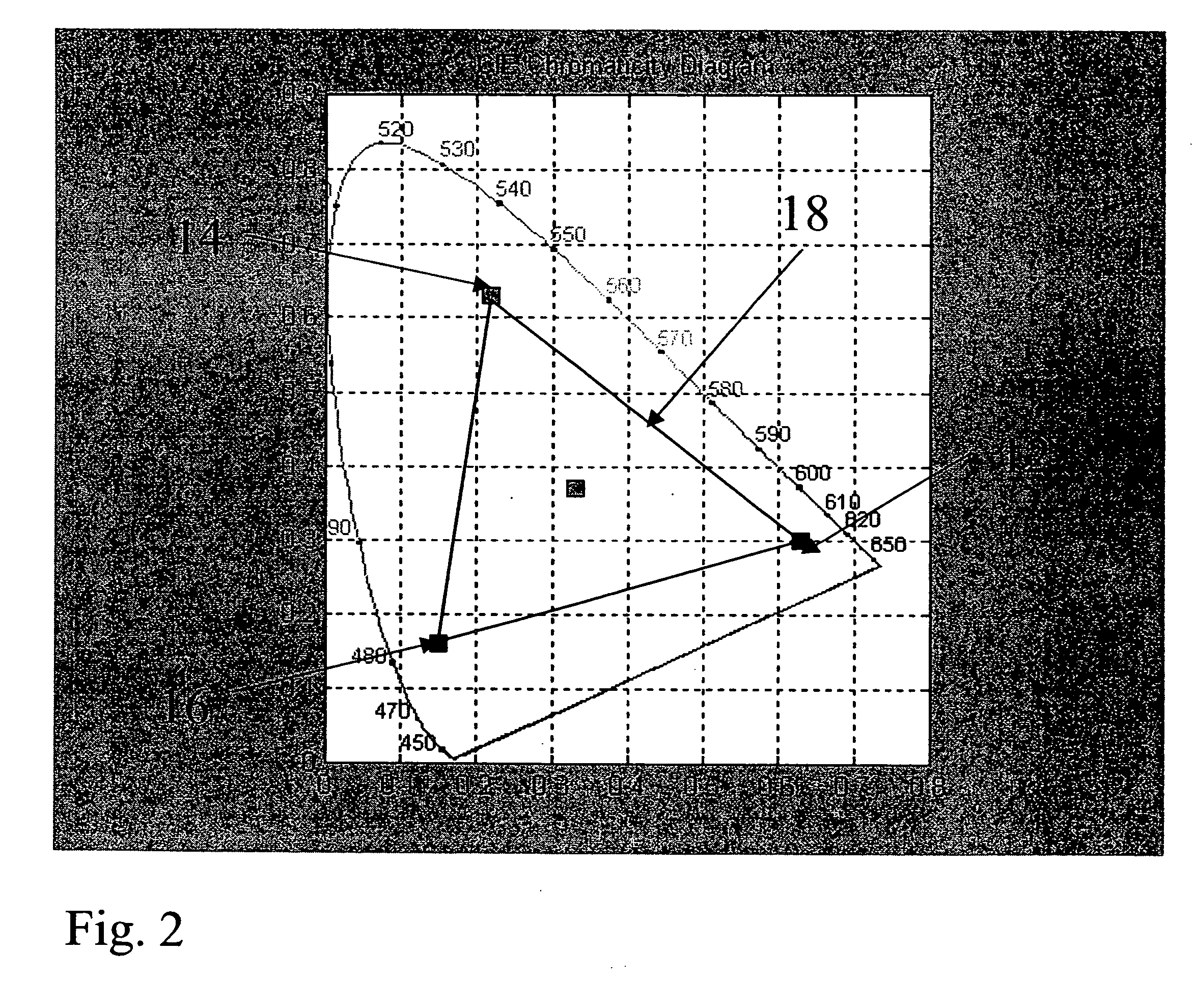
[0035] The additional OLED is ideally positioned within the CIE chromaticity space such that its use may replace a less efficient OLED when forming a color at or near the white point of the display. By meeting this...


PUM


Abstract

An OLED display device includes: an array of light emitting pixels, each pixel having red, green, and blue OLEDs and at least one additional colored OLED that expands the gamut of the display device relative to the gamut defined by the red, green and blue OLEDs, wherein the luminance efficiency or the luminance stability over time of the additional OLED is higher than the luminance efficiency or the luminance stability over time of at least one of the red, green, and blue OLEDs; and means for selectively driving the OLEDs with a drive signal to reduce overall power usage or extend the lifetime of the display while maintaining display color accuracy. In accordance with various embodiments, the present invention provides a color display device with improved power efficiency, longer overall lifetime, expanded color gamut with accurate hues, and improved spatial image quality.

Description

FIELD OF THE INVENTION [0001] The present invention relates to organic light emitting diode (OLED), full-color display devices and, more particularly, to OLED color displays with improved gamut and power efficiency. BACKGROUND OF THE INVENTION [0002] Color, digital image display devices are well known and are based upon a variety of technologies such as cathode ray tubes, liquid crystal and solid-state light emitters, such as Organic Light Emitting Diodes (OLEDs). In a common OLED display device, each display element or pixel, is composed of red, green, and blue colored OLEDs. By combining the illumination from each of these three OLEDs in an additive color system, a wide variety of colors can be achieved. [0003] OLEDs may be used to generate color directly using organic materials that are doped to emit energy in desired portions of the electromagnetic spectrum. However, the known red and blue emissive materials do not have particularly high luminance efficiencies. However, material...

Claims


Application Information

Patent Timeline
Patent Type & Authority Applications(United States)
IPC IPC(8): G09G3/32G09G5/02
CPCG09G3/2003G09G2340/06G09G2300/0452G09G3/3208
Inventor MILLER, MICHAEL E.MURDOCH, MICHAEL J.COK, RONALD S.ARNOLD, ANDREW D.
Owner GLOBAL OLED TECH
Why Eureka
Try Eureka